The trouble is that turning a thin-wall part looks identical to any other lathe job right up until the part comes off the machine. Then you find an oval bore, a waisted OD, or a part that measured perfectly in the chuck and drifted out of tolerance the moment it was released.
This article walks through the exact process route, fixturing decisions, cutting parameters, and troubleshooting fixes that separate a clean thin-wall job from a scrapped one.
Key Takeaways
- Thin-wall parts deform from clamping force, cutting force, and heat combined
- Staged roughing-to-finishing beats simply slowing everything down
- Uneven or excessive clamping pressure causes most out-of-round failures
- Tight cylindricity is achievable with the right fixturing and thermal control
- Pairing precision turning with hardsurfacing expertise pays off on large-diameter, wear-critical parts
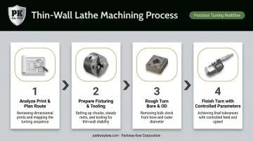
How to Machine Thin-Wall Lathe Parts: Step-by-Step Process
Getting a thin-wall part right depends on sequencing decisions made before the first chip comes off, not just the final finishing pass.
Step 1: Analyze the Print and Plan the Process Route
Start by comparing wall thickness to overall diameter and length. There's no universal ratio that defines "thin wall." A 3mm wall on a 200mm bushing behaves very differently than the same wall on a 25mm sleeve. What matters is whether the part has enough rigidity for the grip and cut you're planning.
From there:
- Map the full process route: blanking, heat treatment, face turning, OD turning, bore turning, inspection
- Set roughing margins based on stiffness, expected springback, and material condition rather than a fixed number pulled from a chart
- Decide early whether you'll need a mandrel, internal support, or auxiliary fixture based on the wall-to-diameter ratio
Step 2: Prepare Fixturing, Support, and Tooling
Fixturing decisions made here determine whether the rest of the job is smooth or a headache.
- Use soft jaws or expanding mandrels that spread clamping pressure across a broader contact area instead of concentrating force at three points
- Convert radial clamping to end-face (axial) clamping wherever the geometry allows; chuck manufacturers report this virtually eliminates radial distortion on thin sections
- Choose the most rigid tool holder your setup allows and keep tool overhang as short as possible to cut vibration
Parkway-Kew applies a related principle on its fracking plunger line: holding the clamping end during finishing, rather than gripping the coated surface, mimics how the part sits in service. This approach has corrected concentricity deviations of up to 0.015 inches that conventional centerless grinding left behind.
Step 3: Rough Turn to Establish Stock and Datums
Rough the bore before finishing the OD. The inner hole is more distortion-prone, so machining it while the outer wall still has extra stock helps maintain overall stiffness through the operation.
- Use moderate depth of cut and feed to limit force-induced deflection while still removing bulk material efficiently
- Apply cutting fluid generously throughout roughing, since uneven heat buildup at this stage compounds into dimensional drift later
- Leave enough OD material in reserve if the ID cut is the harder of the two; that extra stock is what keeps the part rigid
Step 4: Finish Turn with Controlled Parameters and Chip Control
Finishing thin walls means directing force axially instead of radially, which matters more than simply slowing the feed rate.
- Switch to a sharp finishing tool with correct rake angle and chip-breaker geometry so chips clear away from the finished surface
- Take light, controlled finishing passes at higher spindle speed and reduced feed to hold cylindricity
- Cut off or separate the part with a properly ground edge to avoid burring or last-second distortion as support is removed
Sandvik's turning guidance confirms this: a near-90-degree entering angle, a sharp edge, and a depth of cut greater than the tool's nose radius reduce radial force and vibration tendency on thin-walled work.
When Should You Use CNC Turning for Thin-Wall Parts?
Turning isn't automatically the right call for every thin-wall geometry. Fit depends on shape, material, and the tolerance you need to hold.
Turning works well for:
- Rotationally symmetric parts: sleeves, bushings, tubing, cylindrical wear components
- Geometries where cutting forces distribute evenly around the axis
- Large-diameter industrial components like wire drawing blocks, capstans, and festoon wheels
Turning gets riskier for:
- Very high aspect-ratio walls that flex regardless of fixturing
- Non-cylindrical housings where forces can't be balanced around a single axis
- Extremely large-diameter thin sections that exceed standard lathe envelope
These riskier geometries often come down to shop capacity as much as technique. A standard 20-inch chuck lathe tops out well under 20 inches in diameter, fine for small sleeves but not for a wire drawing block.
Parkway-Kew's in-house machining handles parts up to 72 inches in diameter. Dedicated grinding capacity reaches 65 inches in diameter and 12 feet in length, which is why capstans and festoon wheels get built and reground in-house rather than farmed out.
For the non-cylindrical or extremely fragile geometries mentioned above, CNC milling and wire EDM are worth considering instead. Both trade longer cycle times or higher cost for access to shapes turning simply can't reach. Parkway-Kew runs CNC milling in-house alongside its turning and grinding departments for exactly these cases.
Key Parameters That Affect Results When Turning Thin-Wall Parts
Outcomes on thin-wall jobs come down to a handful of controllable variables working together, not one magic setting.
| Parameter | Why It Matters | Impact on Quality |
|---|---|---|
| Spindle/cutting speed | Higher speeds reduce cutting force per pass and carry heat away faster | Too low increases deflection and ovality; too high risks uneven thermal expansion |
| Depth of cut & feed | Larger radial engagement pushes outward on the thin wall | Aggressive depth causes barrel or waist-shape distortion |
| Tool geometry | Larger cutting edge angle, slightly positive rake, and smaller nose radius all reduce cutting resistance | Wrong geometry increases vibration, chatter, and poor chip clearing |
| Clamping force | Uneven pressure distorts the section before cutting even starts | Poor fixture design produces out-of-round parts no matter how good your cutting parameters are |
| Coolant/thermal control | Cutting heat expands the thin wall unevenly during roughing and finishing | Inconsistent cooling causes dimensional drift between process stages |
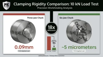
The clamping variable deserves special attention. A 2018 finite-element study on bearing rings modeled three-jaw clamping at 10 kN and predicted 0.09mm of deformation. Switching to a six-jaw configuration under the same load dropped predicted deformation to roughly 5 micrometers — an 18x difference from jaw count alone. That's before cutting force or heat even enter the picture.
Sandvik's cutting-heat data offers a useful reality check too: on average, roughly 80% of cutting heat goes into the chip, 10% into the workpiece, and 10% into the insert. On a thin wall, even that small workpiece share is enough to cause measurable expansion during a cut.
Common Mistakes and Troubleshooting When Turning Thin-Wall Parts
Most thin-wall failures trace back to one of four root causes:
- Skipping process staging: bringing the wall to final size too early removes the support it needed for later cuts
- Excessive or uneven clamping force: the single most common cause of out-of-round parts
- Dull tools or wrong geometry: increases cutting force and invites chatter
- Ignoring thermal effects: under-applying coolant causes dimensional drift between roughing and finishing
Problem: Oval or Waist-Shaped Parts
Likely cause: Uneven force distribution from radial clamping, or oversized roughing cuts that overwhelm the wall's stiffness.
What to check: Review your depth-of-cut staging and switch from radial to end-face clamping wherever the part geometry permits it.
Problem: Chatter Marks or Poor Surface Finish
Likely cause: Excessive tool overhang or overly aggressive cutting parameters.
What to check: Shorten tool stickout, confirm the edge is genuinely sharp, and increase spindle speed while backing off feed rate.
Problem: Dimensional Drift After Unclamping
Likely cause: Residual stress release or elastic deformation from clamping pressure that only shows up once the part is free.
What to check: Re-inspect the part unclamped rather than trusting in-chuck measurements, and reduce clamping force or add a stress-relief step before final finishing.
Conclusion
Thin-wall lathe parts rarely fail because of one bad setting. They fail when planning, fixturing, and cutting parameters aren't treated as one connected system. Get the process route and support strategy right in Steps 1 and 2, and the cutting parameters in Steps 3 and 4 have a far better chance of holding.
Most failures trace back to clamping decisions rather than feeds and speeds. A part clamped unevenly is already distorted before the tool touches it.
For large-diameter, wear-critical components like capstans and wire drawing blocks, machining accuracy is only half the equation. Parkway-Kew pairs precision turning and grinding (up to 72 inches in diameter for machining and 65 inches by 12 feet for grinding) with decades of hardsurfacing experience across coatings like PK-920 and PK-1500. The result: parts hold dimension and resist wear long after they leave the lathe.
Frequently Asked Questions
What is considered a "thin wall" in lathe machining?
There's no fixed thickness threshold. Risk depends on the ratio of wall thickness to diameter and length: a wall that's stable on a small part can be dangerously flexible on a larger one.
Why do thin-walled parts deform during CNC turning?
Three forces cause it: clamping pressure, cutting force from the tool, and heat generated during the cut. Any one of these can push a thin section out of tolerance on its own.
What's the best clamping method for thin-wall lathe parts?
Even, distributed pressure (soft jaws, six-jaw chucks, end-face clamping, or auxiliary support) consistently outperforms high-pressure point clamping from a standard three-jaw setup.
Can you achieve tight tolerances like 0.03mm cylindricity on thin-wall turned parts?
Yes, but it requires the full system: staged roughing and finishing, rigid tooling, and controlled thermal management. One documented case using a specialized eight-finger chuck achieved 0.000084-inch ID roundness on a hardened bearing race.
What materials are hardest to machine as thin-wall lathe parts?
Softer, ductile metals like aluminum and thin-gauge steel tubing deflect easily under force. Harder alloys resist deflection better but generate more heat, which creates its own dimensional problems.
How can you prevent chatter when turning thin-wall components?
Shorten tool overhang, confirm tooling is genuinely sharp, and adjust spindle speed upward while reducing feed. Directing cutting force axially rather than radially also helps cut vibration.