Introduction
High Velocity Oxygen Fuel (HVOF) coating is a thermal spray process that propels heated powder particles onto a substrate at supersonic velocity to form a dense, high-performance protective surface layer.
For maintenance engineers, operations managers, and procurement teams in wire drawing, oil and gas, and heavy industrial manufacturing, that difference in coating density and adhesion has direct consequences. Components in these environments face extreme abrasion, corrosion, and constant mechanical stress that conventional coatings cannot sustain.
When a wire drawing block wears prematurely or a fracking plunger fails mid-operation, the result is unplanned downtime. Siemens estimates that the world's 500 largest companies lose nearly $1.4 trillion annually — equal to 11% of revenues — through unplanned stoppages.
This guide explains how HVOF works, what variables control coating quality, where it outperforms alternatives, and where it falls short. Use it to determine whether HVOF is the right process for your application — or whether a different coating method will deliver better results.
Key Takeaways
- HVOF propels powder particles at 400–800 m/s, creating coatings with porosity below 1% and bond strength exceeding 83 MPa
- Supersonic velocity — not just heat — is what separates HVOF from conventional thermal spray processes
- Wire drawing blocks, fracking plungers, and heavy rotating equipment benefit most from HVOF coatings
- Tightening regulations on hexavalent chromium are driving HVOF adoption as the hard chrome alternative
- HVOF is strictly line-of-sight and requires skilled operation, making it unsuitable for every geometry or failure mode
What Is the HVOF Coating Process?
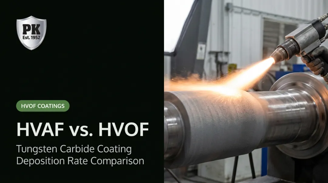
HVOF (High Velocity Oxygen Fuel) is a thermal spray process that emerged in 1982 with the Browning Jet Kote system. Fuel — liquid kerosene or gaseous propane, propylene, or hydrogen — mixes with oxygen and combusts in a chamber, generating a high-pressure, high-temperature gas stream.
Powder feedstock feeds into the nozzle, where particles heat and accelerate toward the workpiece. On impact, they flatten and interlock to form a tightly bonded, dense coating.
What distinguishes HVOF from other thermal spray methods is its emphasis on kinetic energy over thermal energy. Particles arrive at the substrate partially melted rather than fully molten, which preserves beneficial carbide phases and limits oxidation.
How HVOF Compares to Similar Processes
| Process | Particle Velocity | Typical Porosity | Primary Advantage |
|---|---|---|---|
| HVOF | 400–800 m/s | <1% (carbides) | Density, bond strength, hard chrome replacement |
| Plasma Spray | ≤450 m/s | ~1–2% | High-melting ceramics, complex shapes |
| Cold Spray | 300–1,200 m/s | Very low | No heat input, no oxidation |
| Hard Chrome Plating | N/A (electrolytic) | Negligible | Internal diameters, thin functional layers |
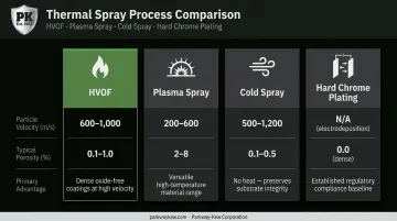
The result is dramatically improved surface hardness, wear resistance, and corrosion protection — all without changing the bulk properties of the base material.
Why HVOF Coating Is Used in Heavy Industrial Applications
The performance demands in high-wear industries are specific and unforgiving.
- Wire drawing blocks and capstans sustain constant abrasive contact with steel wire under high tension. Surface degradation affects the finish quality of the wire being produced.
- Fracking plungers face high-pressure slurry erosion from abrasive proppants at extreme pressures.
- Heavy rotating equipment — crane wheels, rope pulleys, step cones — endures continuous impact and corrosion.
Conventional coatings fail in these environments because they cannot combine the hardness, density, and adhesion that HVOF delivers. Parkway-Kew Corporation recognized this early. In 1989, they introduced HVOF coating for wire drawing blocks, becoming the first to apply the process to this component category. Their four primary HVOF alloys — PK-920 (nickel chrome boron), PK-675, PK-700, and PK-750 — each formulated with progressively higher tungsten carbide content — were developed specifically for this application.
The Cost of Inadequate Surface Protection
Uncoated or inadequately coated components wear rapidly, causing:
- Frequent, costly change-outs
- Surface finish degradation on wire being drawn
- Unplanned production stoppages
Research from tribology literature estimates 23% of global energy consumption originates from tribological contacts, with 3% used to remanufacture worn parts due to wear failures — a figure that underscores why surface protection is not optional in high-contact applications.
Why HVOF Is the Operationally Preferred Choice
According to Oerlikon Metco's thermal spray data, HVOF carbide coatings achieve:
- Porosity below 1% (often under 0.5%)
- Bond strength of 83+ MPa for carbide coatings
A denser coating wears more slowly; higher bond strength means fewer delamination failures in service. Both properties extend service intervals and cut maintenance costs.
There is also a regulatory dimension: OSHA's hexavalent chromium standard sets a permissible exposure limit of 5 µg/m³ for Cr(VI) as an 8-hour TWA, and EU REACH has listed chromium trioxide in Annex XIV, restricting chromium trioxide's use in hard chrome electroplating. Both standards are accelerating the shift toward HVOF — a process that outperforms hard chrome on porosity and adhesion while avoiding the compliance burden entirely.
How the HVOF Coating Process Works
Every stage of the HVOF process directly influences the final coating's properties. The process flow:
Surface preparation → Powder selection → Combustion and spray → Deposition → Post-spray finishing
Step 1: Surface Preparation
Before any powder touches the substrate, the surface must be grit-blasted to create a mechanical anchor profile — a microscale roughness that gives the coating something to grip. Without the correct surface profile, even the best-formulated HVOF coating will delaminate.
Contaminants, oxides, or insufficient roughness are among the most common causes of early coating failure. Surface preparation is not a preliminary step — it is a determinant of coating performance.
Step 2: Combustion and Gas Acceleration
Fuel and oxygen are mixed and ignited in the combustion chamber, generating flame temperatures of approximately 2,600–3,000°C and gas velocities that exceed the speed of sound. The gas stream passes through a converging-diverging nozzle, accelerating powder particles to velocities between 400 and 800 m/s, depending on the gun system and fuel type.
The short dwell time in the flame is deliberate. Particles are softened but not fully melted, which preserves carbide phases that would otherwise dissolve and revert to less useful microstructures.
Step 3: Powder Injection and Particle Impact
Powder is injected into the gas stream (either axially or radially) and accelerated toward the substrate. On impact, particles undergo high-energy plastic deformation, forming thin, disc-shaped "splats" that interlock with each other and with the substrate surface.
The dense stacking of these splats produces HVOF's defining characteristics:
- Low porosity — tightly packed splats leave minimal void space
- High cohesive strength — mechanical interlocking at the splat and substrate level
- Hard, layered microstructure — carbide phases remain intact through the rapid deposition cycle
For carbide-based powders such as WC-Co or WC-Co-Cr, this mechanism preserves the hard tungsten carbide particles within a ductile metallic binder.
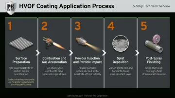
Step 4: Post-Spray Finishing
As-sprayed HVOF coatings are dimensionally rough and must be ground or polished to final tolerances. This step is not cosmetic. Dimensional accuracy and surface finish directly affect how a component performs under load.
This is where in-house grinding capability becomes critical. Parkway-Kew's large-diameter grinding equipment handles components up to 65 inches in diameter and 12 feet in length, with CNC milling and turning capacity up to 72-inch diameter — covering both pre- and post-coating dimensional work on wire drawing blocks and other large rotating parts.
Key Factors That Affect HVOF Coating Quality
Powder Selection and Particle Size
Powder chemistry determines what the coating can do. For most heavy industrial wear applications, the dominant material category is cermets — ceramics in a metallic matrix.
The most widely used HVOF cermet powder is WC-Co-Cr, such as Oerlikon Metco's Woka 3652 WC-10Co-4Cr (particle size -45/+15 µm). TWI testing of this coating found an abrasive wear volume loss of approximately 0.7 mm³ versus 3.2 mm³ for hard chrome — roughly 4 to 5 times better wear resistance.
Parkway-Kew's proprietary HVOF lineup for wire drawing blocks follows the same principle: PK-920 provides nickel chrome boron baseline performance, while PK-675, PK-700, and PK-750 add progressively higher concentrations of tungsten carbide to address increasingly severe wear conditions.
Choosing the right powder, however, is only half the equation. How the material is sprayed determines whether those properties fully transfer into the finished coating.
Spray Parameters
These four variables directly control particle temperature and velocity at impact:
- Fuel-to-oxygen ratio — affects flame temperature and particle heating
- Stand-off distance — influences particle velocity and temperature at the substrate
- Spray angle — affects splat morphology and coating density
- Traverse speed — controls deposit thickness per pass
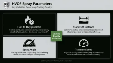
A 2022 peer-reviewed study confirmed that oxygen flow rate and spray distance significantly influence porosity and corrosion resistance. Deviating from optimized parameters leads to increased porosity, delamination, or oxidation — defects that typically require stripping and recoating the part entirely.
Safety and Operational Requirements
HVOF operations generate serious workplace hazards. Relevant OSHA standards governing these operations include:
- Noise (29 CFR 1910.95) — PEL of 90 dBA for 8 hours; hearing conservation required at 85 dBA TWA
- Ventilation (29 CFR 1910.94) — spray rooms must maintain breathing-zone atmospheres within exposure limits
- Air contaminants (29 CFR 1910.1000) — applicable to metal dust and fume
- Respiratory protection (29 CFR 1910.134)
- Chromium (VI) (29 CFR 1910.1026) — PEL 5 µg/m³; action level 2.5 µg/m³
AWS Fact Sheet No. 20 identifies noise, heat, dust, fumes, and mechanical hazards as the primary thermal spray risks. Due to these hazards, HVOF spray guns are typically robot-automated in industrial settings.
HVOF Coating Limitations and When to Consider Alternatives
The Line-of-Sight Constraint
HVOF is strictly a line-of-sight process. The spray gun must have a direct, unobstructed path to the surface being coated, at a distance typically around 300 mm for external diameters. This makes it unsuitable for internal surfaces of small-bore cylindrical components or complex internal geometries.
For internal diameter applications, alternatives retain a clear geometric advantage:
- Pump cylinders and hydraulic bores — hard chrome plating maintains full coverage
- Small valve bodies — electroless nickel suits the geometry where HVOF cannot reach
- Tight-tolerance bores — chemical deposition methods avoid the access constraints entirely
Thickness Is Not Always Better
Residual stress accumulates with every additional HVOF layer — thickness limits are material-specific. Research on various coating systems shows that exceeding the optimum thickness for a specific coating-substrate pair can trigger spallation.
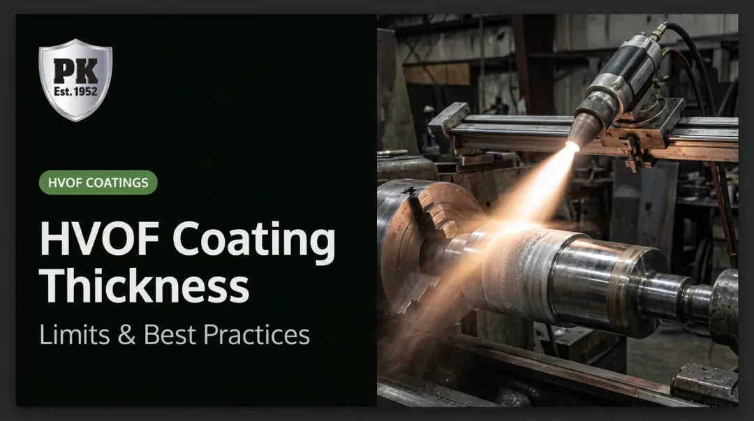
For most wear applications, coatings in the range of 0.1–0.5 mm are appropriate. Going beyond this range without an engineering evaluation invites spallation failure rather than preventing it.
When HVOF Is the Wrong Choice
HVOF should not be the default answer for every wear problem. Specific situations where alternatives are more appropriate:
- Small, complex-geometry parts on a limited budget — HVOF setup costs and process requirements may not be justified
- Internal bore applications — hard chrome or electroless nickel coatings are better suited
- Very large wire drawing blocks — metallizing (PK-400) is the proven choice where HVOF cannot deliver adequate build-up
- High-speed ferrous wire drawing with plated wire — plasma spray ceramic (PK-1500 chrome oxide) can be more cost-effective
- Impact fracture failure modes — if a component fails due to impact rather than abrasive wear, sub-arc hardfacing (such as Parkway-Kew's sub-arc process with PK-503 or PK-200) may outperform HVOF by delivering a tougher, more impact-resistant deposit
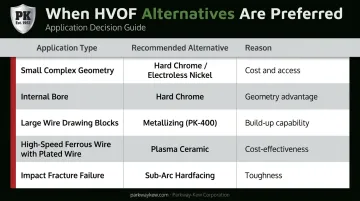
The failure mode determines the right process. Matching the coating method to how a component actually fails — abrasion, corrosion, or impact — is what separates a successful rebuild from a repeat repair.
Conclusion
HVOF coating works because supersonic particle impact creates a microstructure that other processes cannot replicate at the same combination of density, hardness, and bond strength. For components that fail by abrasive wear or corrosion — wire drawing blocks, fracking plungers, heavy rotating equipment — it is among the most effective surface engineering tools available.
But the process leaves little room for error: surface preparation, parameter control, geometry compatibility, and post-spray finishing all determine whether a coating performs or fails. A misapplied spec — wrong powder for the substrate, insufficient surface prep, incompatible geometry — typically results in premature delamination or coating failure, and a component that needs to come back off the line sooner than it should.
If you are evaluating HVOF for specific components, the most reliable next step is consulting a specialist who has applied the process across a range of substrates, industries, and failure modes — not just one application type. Parkway-Kew Corporation has been doing exactly that since 1989, when they introduced HVOF coating for wire drawing blocks, years before it became standard practice across the industry.
Frequently Asked Questions
What is the HVOF coating process?
HVOF is a thermal spray process where fuel and oxygen combust to produce a supersonic gas jet that propels powder particles onto a substrate at 400–800 m/s. The high-velocity impact forms a dense, hard, low-porosity coating used to improve wear and corrosion resistance on industrial components.
What is the maximum thickness of HVOF coating?
For most wear applications, HVOF coatings are applied in the 0.1–0.5 mm range. Thicker deposits are achievable in some material systems, but residual stress accumulates with thickness. Exceeding the optimum for a given material-substrate combination increases the risk of spallation.
What are the alternatives to HVOF coating?
The four main alternatives each suit different constraints:
- Plasma spray — higher porosity, better suited to ceramics and complex shapes
- Hard chrome plating — effective for internal diameters, though hexavalent chromium regulations limit its use
- Cold spray — no heat input, but restricted to ductile materials
- Sub-arc weld overlay hardfacing — preferred for thick build-up and impact-resistant applications
What materials can be applied using the HVOF coating process?
HVOF handles cermets (WC-Co, WC-Co-Cr, Cr₃C₂-NiCr), metal alloys (nickel, cobalt, stainless steel), pure metals, and select ceramics and composites. Cermets are the most common choice for industrial wear applications due to their combination of hardness and toughness.
How does HVOF coating compare to hard chrome plating?
HVOF carbide coatings achieve 4–5 times lower abrasive wear volume loss than hard chrome in direct testing. For external geometries, HVOF is the superior option. Hard chrome retains an advantage on internal diameters and complex bores, though increasing regulatory restrictions on hexavalent chromium are narrowing the cases where it remains the preferred choice.