Get the diagnosis wrong and you'll pick the wrong alloy, the wrong coating, or the wrong repair method. That mistake gets expensive fast. Corrosion costs the global economy more than $2.5 trillion annually, according to AMPP's 2025 update on the ongoing corrosion crisis, a figure built on NACE's original 2013 global GDP baseline.
This guide breaks down how pitting and crevice corrosion form, where each one shows up, and what actually works to stop them, including alloy selection and protective coatings.
Key Takeaways
- Pitting creates narrow, deep cavities on exposed surfaces
- Crevice corrosion spreads wider, shallower damage inside confined gaps
- Both start with a breakdown of the passive oxide film, usually triggered by chloride exposure
- The Pitting Resistance Equivalent Number (PREN) helps predict alloy resistance to both attack modes
- Effective prevention blends alloy selection, smart design, and coatings like HVOF and thermal spray
Pitting vs Crevice Corrosion: Quick Comparison
Before covering the underlying mechanisms, here's the side-by-side breakdown industrial teams actually need for troubleshooting.
| Factor | Pitting Corrosion | Crevice Corrosion |
|---|---|---|
| Location of Attack | Open, exposed surfaces where chloride-rich droplets pool or evaporate | Hidden spots: under gaskets, beneath clamps, inside deposits, or between overlapping surfaces trapping fluid |
| Severity & Penetration | Narrow, deep cavities that can perforate a tube wall in a surprisingly short time | Wider, shallower spread covering more surface area but advancing slower per attack site |
| Common Triggers | Stagnant chloride droplets, evaporating saltwater films, warm and humid conditions | Oxygen-depleted stagnant fluid trapped in tight gaps, plus deposit or sludge buildup |
| Detection Difficulty | Sometimes leaves a visible entry point, though subsurface damage often runs deeper than it looks | Stays hidden until you physically remove the clamp, gasket, or fitting causing it |
What is Pitting Corrosion?
Pitting corrosion is a localized breakdown of the passive chromium oxide film that produces small, deep cavities on otherwise exposed stainless steel surfaces. It doesn't spread evenly. It concentrates.
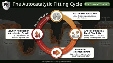
Here's the mechanism: once the passive film fails at one point, that tiny spot becomes an anode surrounded by a much larger cathodic surface. That mismatch drives an autocatalytic reaction, meaning the pit essentially feeds itself.
Metal dissolves, chloride ions migrate in to balance the charge, and the trapped solution acidifies. Each cycle makes the pit grow faster than the last one.
This matters beyond surface damage. Pits under tensile stress can act as initiation sites for stress corrosion cracking, a serious concern in pressurized systems where a single crack can lead to sudden failure rather than a slow leak.
Visual identification isn't always straightforward. Look for:
- Reddish-brown iron oxide deposits around small surface openings
- Perforations that look minor on the surface but run deeper underneath
- Upward-facing surfaces where chloride water pools and evaporates, concentrating salts
Use Cases of Pitting Corrosion
Pitting shows up most often in offshore and marine tubing, oil and gas process instrumentation, and food or chemical processing equipment exposed to chloride-rich environments.
A well-documented example: a Gulf of Guinea floating production facility had to replace roughly 8 km (5 miles) of 316L instrument tubing, at a cost exceeding $5 million, after pinhole leaks appeared less than six months into service.
Investigators traced the failure to external pitting and crevice corrosion, worsened by molybdenum content sitting near the low end of the allowable 316L range (full case detailed by Offshore magazine).
Machine parts in wire mills and fracking operations face comparable chloride and moisture exposure. That's part of why wear-resistant hardfacing matters on these surfaces.
Parkway-Kew applies coatings like PK-730 tungsten carbide on fracking plungers operating in harsh, chemically aggressive downhole conditions, and HVOF-applied tungsten carbide coatings (PK-675, PK-700, PK-750) on wire drawing blocks and capstans exposed to similar wear and corrosion stress.
What is Crevice Corrosion?
Crevice corrosion is localized attack that occurs in narrow, oxygen-restricted gaps where stagnant fluid gets trapped and can't be refreshed. No flow, no fresh oxygen, no self-repair of the passive film.
The mechanism starts with differential aeration. Oxygen depletes inside the crevice faster than it does on the exposed surface nearby, so the crevice becomes anodic relative to that surface.
Chloride ions then migrate inward to balance the charge, and the trapped solution acidifies. The protective oxide layer breaks down right where you can't see it happening.
Common crevice locations include:
- Gaps between tubing and supports or clamps
- Space under gaskets and seals
- Areas beneath deposits or sludge buildup
- Incomplete weld penetrations
You'll sometimes hear crevice corrosion grouped with Corrosion Under Pipe Supports (CUPS) in piping systems, since support contact points frequently create the same trapped-moisture geometry. CUPS describes a failure location rather than a strict synonym for crevice corrosion; it can involve crevice mechanisms, but not exclusively.
Use Cases of Crevice Corrosion
Crevice corrosion turns up wherever components touch, overlap, or trap fluid: tubing-to-clamp connections, pipe supports, and marine structures with overlapping parts.
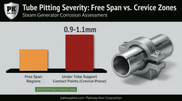
Nuclear steam generator tubing shows this pattern clearly. IAEA data on WWER steam generators found pitting as the dominant degradation mode both in free spans and beneath tube supports, with destructive examinations recording pit depths of 0.9 to 1.1 mm at these crevice-prone contact regions (IAEA TECDOC-1577). Support contact points create exactly the kind of oxygen-restricted microenvironment that drives this attack.
This mode is especially relevant for tight-fitting wear components like drawing blocks, capstans, and festoon wheels in wire mills and shipping terminal equipment, where moisture and debris collect at contact points between moving and stationary parts.
Pitting vs Crevice Corrosion: Which Is Worse and How to Prevent Both
Neither corrosion type wins the "worse" title outright. The real answer depends on four factors: alloy chemistry, chloride and temperature exposure, component design, and what happens if the part actually fails.
Situational guidance: Pitting tends to be the bigger concern on exposed surfaces in chloride-heavy environments, like offshore decks and marine equipment. Crevice corrosion is the bigger risk anywhere parts touch, overlap, or trap moisture, such as clamps, gaskets, and machine assemblies.
Using PREN to Compare Alloys
The Pitting Resistance Equivalent Number (PREN) uses the formula %Cr + 3.3 × %Mo + 16 × %N to rank an alloy's composition-based resistance to localized attack. Higher numbers mean better resistance to both pitting and crevice corrosion, though PREN alone doesn't guarantee service performance.
| Alloy | Typical PREN | Relative Resistance |
|---|---|---|
| 304L | 18 | Baseline, lowest resistance |
| 316L | 24 | Moderate improvement over 304L |
| Super-duplex 2507 | 42–43 | Strong resistance to both attack modes |
| 6Mo (254 SMO) | 42–43 | High resistance; strong CPT/CCT results in lab testing |
Lab data under ASTM G48 testing (critical pitting temperature and critical crevice temperature) confirms these rankings, though results vary by surface finish, weld condition, and test method. Don't compare CPT figures from one testing method against CCT figures from another; they're not measuring the same thing.
Design-Based Prevention
- Eliminate unnecessary gaps and sharp corners where fluid can stagnate
- Ensure proper sealing and drainage so moisture doesn't sit against the metal
- Minimize overlapping or touching surfaces wherever the application allows it
Coating-Based Prevention
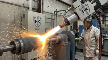
Engineered coatings create a dense barrier between the substrate and the corrosive environment. HVOF (High Velocity Oxygen Fuel) coatings apply alloy powder at speeds exceeding Mach 2, producing a hard, virtually defect-free surface with minimal porosity, exactly the kind of gap corrosive agents would otherwise exploit.
Parkway-Kew's HVOF lineup (PK-675, PK-700, PK-750) escalates tungsten carbide content to match coating hardness to the severity of the operating environment.
Plasma spray ceramic coatings, like Parkway-Kew's PK-1500 chrome oxide, offer a chemically inert barrier suited to high-speed, high-friction applications. For the harshest oil and gas conditions, the proprietary PK-730 fused tungsten carbide coating creates a metallurgically bonded barrier engineered specifically for fracking plunger service.
Cathodic protection, whether sacrificial anode or impressed current, serves as a supplementary method for large pipelines, storage tanks, and marine structures. It doesn't replace alloy selection or good design, but it adds a layer of protection where those structures sit in constant contact with corrosive water.
Conclusion
Neither pitting nor crevice corrosion is universally worse. The right prevention strategy depends on where a component sits, what it's exposed to, and how it's designed. Exposed surfaces in chloride-rich environments call for pitting-focused solutions. Anywhere parts touch, overlap, or trap moisture, crevice corrosion becomes the priority.
Getting the alloy, design, and coating choices right directly affects unplanned downtime, leak risk, and maintenance cost for operators running equipment in oil and gas, wire drawing, and marine environments. These are the same industries Parkway-Kew has served with wear-resistant coatings since 1952. A correctly specified coating or component rebuild, applied before failure rather than after, tends to be the cheaper path either way.
Frequently Asked Questions
What is crevice corrosion?
Crevice corrosion is localized corrosion that occurs in confined, oxygen-restricted gaps where stagnant fluid becomes trapped and can't be renewed. It typically forms under gaskets, clamps, or deposits.
What is pitting corrosion?
Pitting corrosion is localized attack that forms small, deep cavities on exposed metal surfaces after the passive chromium oxide layer breaks down at a specific point.
How do you stop crevice corrosion?
Select higher-PREN alloys, redesign components to eliminate gaps and stagnant zones, and apply protective coatings like HVOF or plasma spray to create a continuous barrier.
How do you repair crevice corrosion?
Assess the pit depth, remove the affected material, then weld-repair or replace the component as needed. Reapply a protective coating afterward to prevent recurrence.
What is another name for crevice corrosion?
In piping systems, it's often grouped with Corrosion Under Pipe Supports (CUPS), since support contact points frequently create similar trapped-moisture conditions.
Which is more dangerous, pitting or crevice corrosion?
Pitting typically penetrates faster and deeper, raising the risk for pressurized systems. Crevice corrosion is harder to manage since it hides beneath contact points until inspection.