Introduction
HVOF coating thickness is a design variable, not a byproduct of spraying. Nail it and you get the wear life, corrosion resistance, and bond integrity the application demands. Misjudge it in either direction — too thin or too thick — and the coating fails before the component reaches its intended service interval.
Engineers specifying thermal spray coatings on industrial components — wire drawing blocks, fracking plungers, pump plungers, crane wheels — need to understand what controls HVOF thickness limits before locking in a spec. Published ranges like "0.1–0.5 mm" exist, but they're starting points, not universal mandates.
The actual ceiling for any given coating is set by residual stress physics, material ductility, substrate geometry, and how the coating is processed after spraying.
This article covers the mechanisms behind HVOF thickness limits and what the research literature says about typical and extreme values. It also addresses how thickness interacts with porosity and hardness, and the specification errors that most commonly cause problems in practice.
Key Takeaways
- HVOF cermet coatings (WC/Co, Cr₃C₂/NiCr) are typically specified at 200–350 microns; metallic alloys may build higher under qualified conditions
- Metallic alloy coatings can exceed cermet thickness limits when process parameters and substrate conditions are properly controlled
- Thickness limits are governed by residual stress accumulation — not arbitrary rules — and failure modes include delamination, cracking, and spalling
- Thicker is not better: full wear and corrosion protection is achievable at modest depths, and exceeding the ceiling adds risk without performance gain
- As-sprayed thickness and post-grind finished thickness are separate specifications — always define grinding allowance before setting your target
- Field gauges and lab cross-sections serve distinct verification purposes and both are required
What HVOF Coating Thickness Represents and What Governs Its Limits
HVOF thickness is the total depth of thermally sprayed material deposited on the substrate surface. It functions simultaneously as a design specification (stated on engineering drawings), a process variable (controlled via spray passes and gun parameters), and a derived characteristic (verified after application and finishing). Confusing these three roles is one of the most persistent sources of specification errors.
How the Splat Structure Creates a Thickness Ceiling
In the HVOF process, powder particles are accelerated to supersonic velocities in a combustion stream, strike the substrate, flatten, and solidify within microseconds. Each successive pass deposits another lamellar layer — and with each layer, residual stress accumulates within the coating structure.
This cumulative stress is what imposes the practical thickness ceiling. Research by Stokes and Looney confirmed that residual stress buildup in HVOF WC-Co thick deposits can cause adhesion loss, interlaminar debonding, crack formation, and buckling — with stress state changing measurably as deposit thickness increases. A separate study by Xu et al. (2025) reported that residual stress in HVOF WC coatings increased from 525.67 MPa to 868.29 MPa with increasing thickness.
Factors That Set the Upper and Lower Limits
Material ductility and hardness set the primary constraint. Cermet coatings like WC/Co and Cr₃C₂/NiCr are inherently brittle, meaning residual stress cannot be relieved through plastic deformation the way it can in softer metallic alloys. The coating reaches its cohesive strength limit at lower accumulated thickness than a ductile metallic system would.
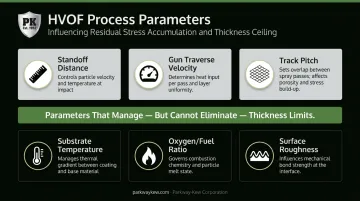
Process parameters shift the ceiling, but only within defined bounds. The following all influence how quickly internal stress accumulates:
- Standoff distance (standard ~170 mm for WC-12Co systems)
- Gun traverse velocity (~300 mm/min in documented studies)
- Track pitch (~4 mm)
- Substrate temperature during spraying
- Oxygen/fuel ratio (affects in-flight particle velocity and temperature)
- Substrate surface roughness — grit-blast-induced texture directly affects adhesion, as confirmed by Staia et al. for HVOF WC-17Co coatings
Adjusting these parameters can optimize the stress state at a given thickness, but they don't eliminate the fundamental physical constraint. They manage it. Specifying thick cermet coatings without adequate substrate roughening and adhesion qualification is a setup for early failure.
HVOF Coating Thickness Range: Typical Values and Hard Limits
Nominal Operating Range
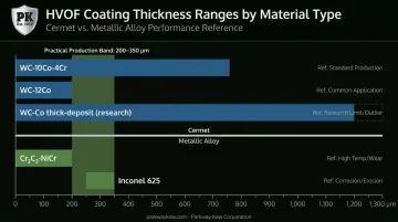
Published HVOF thickness data in the peer-reviewed literature clusters more tightly than the broad "0.1–0.5 mm" range often cited in general references:
| Coating Material | Documented Thickness | Source |
|---|---|---|
| WC-10Co-4Cr cermet | 350 µm nominal | TWI hard-chrome replacement study |
| WC-12Co cermet | 200 µm (dense, homogeneous) | Selvadurai et al. |
| WC-Co (thick-deposit study) | Up to 1.2 mm (research geometry) | Stokes & Looney |
| Cr₃C₂-NiCr | 0.2 mm | Comparative HVOF study |
| Inconel 625 | 250–350 µm | Boudi et al. |
The practical takeaway: cermet HVOF coatings in production applications commonly land in the 200–350 µm range, not at the upper end of the theoretical 500 µm window.
Upper Limits and Why They're Not Universal
No authoritative source confirms a universal delamination threshold at exactly 0.5 mm for WC-Co. What the literature confirms is that the upper limit is material-, substrate-, geometry-, and process-dependent.
Key findings from the research bear this out:
- Selvadurai et al. found that increasing coating thickness and substrate temperature elevated stresses in HVOF WC-12Co — with unfavorable stress states capable of causing delamination and spallation
- HVAF (High Velocity Air Fuel) systems produce a more ductile splat structure, tolerating greater thickness buildup for equivalent cermet materials — worth evaluating when significant build-up is required
Because the right limit depends on the specific combination of material, substrate, and geometry, optimal thickness for any given application — whether wire drawing blocks, fracking plungers, or other wear components — should be established through engineering consultation rather than taken directly from a published table. Parkway-Kew Corporation has been applying HVOF coatings to these applications since 1989.
How Thickness Shapes HVOF Coating Performance
Thickness doesn't independently determine performance. It interacts with porosity, hardness, bond strength, and surface finish. The sections below break down how each interaction affects the final coating — and where thickness decisions go wrong.
Porosity and Through-Coating Integrity
Below a minimum effective thickness, residual porosity channels within the lamellar structure can interconnect through the full coating depth. Once that happens, corrosive media reaches the substrate and wear resistance is compromised — regardless of surface hardness.
Porosity values in HVOF coatings vary significantly by material and process:
- HVOF Hastelloy C: open porosity below 0.1 vol% (measured by ICP atomic emission spectrometry)
- HVOF Inconel 625: 1.5–4.5% porosity
- HVOF WC-Co + Cr: approximately 4% in one documented study
The commonly cited "1–2 vol%" for WC-Co coatings was not confirmed in the peer-reviewed literature reviewed here. Porosity targets should be verified against material-specific data or manufacturer datasheets, not assumed from general HVOF claims.
Residual Stress Gradients Through the Coating Depth
As HVOF coating thickness increases, residual stress does not accumulate uniformly. Santana et al. found that as-ground WC-12Co coatings showed compressive surface stresses but tensile stress peaks at depths of 50–125 µm below the surface. These subsurface tensile regions can initiate cracking under cyclic load — making thickness management especially important on components subject to fatigue or thermal cycling.
Bond Strength, Cohesive Strength, and Failure Mode
Those stress gradients also affect how the coating ultimately fails. HVOF coatings are capable of achieving adhesive bond strength exceeding 80 MPa (coating-to-substrate), but thicker deposits don't improve this figure. They can reduce effective cohesive strength (the inter-layer bond within the coating itself), shifting the failure mode from substrate separation to inter-layer delamination.
Grinding Allowance: The Specification Detail Most Often Missed
Most precision HVOF-coated components are ground after spraying to achieve dimensional tolerances and surface finish requirements. This requires two separate thickness specifications:
- Finished (post-grind) thickness — the governing dimensional requirement
- As-sprayed thickness — the target during application, which must be higher to account for stock removed during grinding (typically 0.05–0.10 mm grinding allowance)
Failing to define both leads to one of two problems: the grinder removes too much material, pushing the component below minimum thickness, or the specification calls for excessive as-sprayed build-up that drives unnecessary cost and residual stress.
Our in-house grinding capacity — up to 65 inches diameter by 12 feet length — is integrated directly into the HVOF workflow for this reason. Our Restore & Grind process for wire drawing blocks engineers coating thickness from the start to accommodate multiple grinding cycles over the component's service life.

Specifying and Measuring HVOF Coating Thickness
Specification and Documentation
Engineering drawings and coating procedure specifications should define finished (post-grind) thickness as the governing requirement. As-sprayed targets are then derived from it, incorporating the grinding allowance.
Referencing applicable standards adds traceability:
- ASTM E376 — electromagnetic (eddy current / magnetic induction) coating thickness measurement
- ASTM B487 — local thickness by metallographic cross-section
- ISO 14916 — tensile adhesive strength of thermally sprayed coatings (not a thickness method, but relevant for adhesion qualification tied to thickness limits)
Measurement Methods
| Method | Type | Best Use |
|---|---|---|
| Eddy current gauging | Non-destructive | Non-conductive coatings on conductive substrates; fast, field-deployable |
| Magnetic induction | Non-destructive | Ferromagnetic substrates; production QC |
| Metallographic cross-section (ASTM B487) | Destructive | Definitive thickness, porosity, and bond quality verification |
| Ultrasonic | Non-destructive | Emerging field option; accuracy for HVOF coatings not yet standardized |
Field vs. Lab Measurement
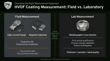
Field instruments measure spot thickness at discrete points. They confirm dimensional compliance but tell you nothing about porosity distribution, microstructure, or inter-layer bond quality beneath the surface.
Cross-section metallographic analysis is required when coating integrity — not just dimensional compliance — needs to be verified. Use it for:
- First-article qualification before approving a new coating run
- Process change validation when parameters or materials shift
- Failure investigation when a coating underperforms in service
Field gauges belong in production QC. Metallographic analysis belongs at qualification gates. Knowing which tool answers which question prevents gaps in your quality chain.
Consequences of Incorrect HVOF Coating Thickness
Under-Thickness
A coating below the minimum effective depth delivers predictable, avoidable failures:
- Porosity channels extend through the full coating depth, allowing corrosive media to reach the substrate
- Abrasive wear penetrates the coating before the intended service interval is reached
- Target surface hardness profile is not achieved — the component performs below spec from day one
- Result: premature replacement, unplanned downtime, and recoating costs that exceed what a correct specification would have required
Over-Thickness
Exceeding the recommended upper limit introduces a different class of problems:
- Progressive residual stress accumulation beyond the coating's cohesive strength threshold
- Delamination or spalling — triggered at the most demanding service point (thermal cycling, impact, fluctuating load)
- No performance gain over a correctly specified coating — just added cost and post-processing time
Common Specification Errors
Three mistakes appear repeatedly in HVOF thickness specifications:
Over-specifying from published ranges — published ranges are design windows, not mandatory targets. Applying 500 µm because that's the top of the published range, regardless of actual application requirements, adds cost without adding performance.
Ignoring geometry in line-of-sight processes — HVOF cannot reach recessed profiles, internal diameters, and sharp edges the same way it coats flat surfaces. Wire drawing block drawline grooves are a direct example: the groove geometry creates measurable variation in deposit thickness that lab-verified flat-surface values won't predict.
Conflating as-sprayed and finished thickness — specifying "0.3 mm coating" without stating whether that's before or after grinding causes disputes between specifiers and applicators. Define both values explicitly in every specification.
Conclusion
HVOF coating thickness is a primary engineering variable. It governs wear life, corrosion protection, bond integrity, and failure mode. That means specifying thickness alongside material selection, surface preparation, and post-processing — not as an afterthought once those decisions are already made.
Published ranges are a starting point. Residual stress physics, material-specific ductility limits, and geometry-driven spray access constraints all shift what those numbers mean for a specific component. A nominal range from a datasheet won't account for any of that on its own.
For applications with demanding requirements — high-pressure fracking plungers, continuous wire drawing contact, or components that go through multiple service cycles — involving an HVOF coating specialist at the specification stage, rather than after a failure, is where thickness gets defined correctly. Parkway-Kew has been doing exactly that since introducing HVOF for wire drawing blocks in 1989.
Frequently Asked Questions
What is the typical thickness of HVOF coating?
HVOF cermet coatings (WC/Co, Cr₃C₂/NiCr) typically fall in the 200–350 µm range in production, with the broader industry window extending to 0.5 mm (500 µm). Metallic alloy coatings can build higher. Optimal thickness depends on the material, application load, and whether post-spray grinding is required.
What are the properties of HVOF coating?
HVOF coatings are characterized by very high hardness (WC-Co typically 1,100–1,600 HV), high bond strength, low oxide content, and very low porosity relative to other thermal spray processes. These properties are achieved together within the correct thickness window — no single property can be optimized in isolation from the others.
What causes HVOF coating thickness limits?
Thickness limits arise from residual stress accumulation in the lamellar splat structure. As successive layers build up, internal stress grows until the coating's cohesive strength is exceeded, causing cracking, delamination, or spalling. Material ductility, spray parameters, and substrate geometry all influence where that ceiling falls for a given coating system.
Is thicker HVOF coating always better for wear resistance?
No. Full wear protection is typically achieved well within the nominal thickness range. Applying coating beyond the recommended maximum increases residual stress and delamination risk without improving wear life. Once the minimum protective depth is reached, additional thickness adds cost and failure risk, not performance.
How is HVOF coating thickness measured?
Eddy current and magnetic induction gauges (per ASTM E376) are the standard non-destructive field methods. Cross-section metallographic analysis (per ASTM B487) is the definitive lab method, providing dimensional verification alongside porosity, bond quality, and microstructure data — required for first-article qualification.
What happens if HVOF coating is applied too thin?
Under-thickness allows porosity channels to connect through the full coating depth, undermining both corrosion and wear protection. The component fails to reach its designed service interval, requiring recoating or early replacement — at costs that a correct initial specification would have avoided.