Surface finish terminology trips up even experienced engineers. Ra, Rz, microinches versus microns, checkmark symbols carrying five or six different fields, the vocabulary alone can stall a drawing review before anyone gets to the actual design problem.
This guide breaks down what surface finish really means, how it's measured, how to read the symbols on a print, and why it matters most in demanding industrial settings like wire drawing and oilfield equipment.
Key Takeaways
- Surface finish has three traits: roughness, waviness, and lay, not just a single Ra number
- Ra and Rz measure different things; don't swap them without checking the governing standard
- Contact profilometers and optical scanners suit different inspection needs
- Specify the roughest tolerable finish to keep machining costs and lead times down
- In wire drawing, block and capstan finish transfers directly onto the wire
What Is Surface Finish?
Surface finish, also called surface texture, describes the geometric character of a machined or coated surface. Two standards govern how it's specified and measured in the US: ASME Y14.36-2018 covers how texture requirements get shown on drawings, and ASME B46.1-2019 defines the terminology, parameters, and measurement practice itself.
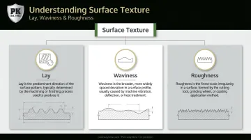
Surface texture splits into three separate characteristics. Confusing them is one of the most common mistakes on a print.
Lay
Lay is the direction of the dominant pattern left by whatever process made the surface. Turning leaves circular lay; milling can leave parallel or crosshatched lay. Common lay types include:
- Parallel
- Perpendicular
- Crosshatched or angular
- Multidirectional
- Circular
- Radial
- Particulate or nondirectional
Two surfaces with identical Ra values can behave very differently in service if their lay doesn't match the direction of motion or fluid flow.
Waviness
Waviness refers to broader, more widely spaced variations in a surface, typically caused by machine chatter, tool deflection, or thermal distortion during processing. It's measured over its own evaluation length, separate from roughness, and matters most in fatigue-sensitive or sealing applications, where a wavy surface can print through a gasket or coating.
Surface Roughness
Roughness is the finest-scale texture, the closely spaced marks left directly by a cutting tool, grinding wheel, or spray pattern.
In everyday shop talk, "surface finish" usually just means roughness, since it's the characteristic most often measured and called out on a drawing. That shorthand works fine day to day, but it causes real problems when waviness or lay is actually driving the functional issue.
Understanding Ra and Rz: The Two Most Common Roughness Parameters
Two parameters dominate roughness callouts on prints: Ra and Rz. They are not interchangeable, and treating them as such is a common and costly mistake.
Ra (arithmetic average roughness) is the mean of the absolute deviations of the roughness profile from the centerline, averaged over the evaluation length. It's the default parameter on most U.S. drawings.
Rz (mean roughness depth) takes a different approach. It averages the five largest peak-to-valley deviations found across five consecutive sampling lengths.
Because it reacts to extremes rather than an average, Rz picks up isolated scratches or defects that Ra can smooth over. That sensitivity makes it the parameter of choice on most international drawings.
Converting Between Ra and Rz
A commonly cited rule of thumb estimates Rz at roughly 7.2 times the Ra value. Treat this as a rough planning estimate only. No ASME or ISO standard endorses it as a fixed conversion, and leaning on it for inspection acceptance can get you into trouble. Always confirm which parameter, standard, and cutoff length a print actually specifies.
Units matter just as much as the ratio. American drawings typically specify roughness in microinches, while international drawings use micrometers, or microns. The conversion between them is fixed: one microinch equals 0.0254 micrometers, since one inch equals exactly 25.4 millimeters.
What Does 3.2 Ra Actually Mean?
A callout of 3.2 µm Ra (about 126 microinches) is one of the most common as-machined finishes in industry. Hubs lists it as their standard CNC machining finish, with light but visible tool marks and occasional scratches. It's a practical, cost-effective baseline for surfaces that don't need additional finishing operations.
Typical Ra Ranges by Process
| Process | Typical Ra Range | Notes |
|---|---|---|
| Casting | Highly variable | Depends heavily on mold, pattern, and material |
| Standard CNC machining | 1.6-3.2 µm | 3.2 µm is the common as-machined default |
| Fine machining | 0.4-1.6 µm | Tighter tool control, slower feeds |
| Grinding | 0.1-2 µm | Wide envelope depending on wheel and passes |
| Honing/lapping | 0.006-0.4 µm | Used for bores and precision mating surfaces |
| As-sprayed thermal coating | 5-20 µm | Rough as deposited, often ground afterward |
Parkway-Kew's grinding lines, built to handle parts up to 65 inches in diameter, hold finishes in that 0.1-2 µm grinding range daily, tight enough for wire drawing block bores and other close-tolerance mating surfaces.
How Surface Finish Is Measured
Once a finish is specified, it has to be verified. Three methods cover most shop-floor and lab needs.
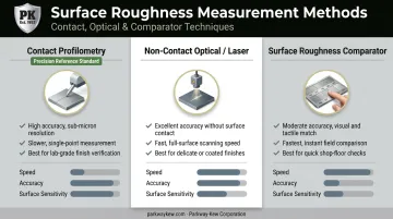
Contact profilometry uses a stylus with a known tip radius that drags across the surface, recording height changes as it travels. It's accurate and quantitative, but it samples only a single line, moves slowly, and can mark soft or coated surfaces.
Non-contact methods, including optical or laser profilometry and interferometry, scan the surface without touching it. These are preferred when:
- The surface is soft, coated, or otherwise damage-sensitive
- A full 3D map is needed instead of a single line trace
- Fast, high-volume inspection is required
Results between contact and optical methods aren't always identical, so match the method to what the drawing calls for.
Surface roughness comparators offer a simpler option: calibrated specimens a technician compares against the workpiece by sight and touch. They're handy for quick shop-floor screening but aren't a substitute for instrumented data when a print specifies a numeric Ra or Rz limit.
Restoration shops like Parkway-Kew rely on these same methods to confirm reground surfaces meet the Ra or Rz specified on the original print.
Reading Surface Finish Symbols on Technical Drawings
The basic surface finish symbol is a checkmark placed on the surface line, extension line, or feature control frame of a print. Three variants control material removal:
- Plain checkmark: material removal by any method is allowed
- Checkmark with a bar: material removal is required
- Checkmark with a circle: material removal is prohibited, common on as-cast, as-forged, or coated surfaces
The Full Symbol Breakdown
A complete surface finish symbol can carry up to six pieces of information positioned around the checkmark, though most shop prints use only two or three of these fields:
- Roughness value (typically Ra) at the top-left
- Production method or treatment note above the horizontal line
- Sampling or cutoff length below the value
- Lay direction symbol at the bottom
- Minimum material removal allowance, if specified
- A secondary parameter, such as Rz, when one value isn't enough
Not every field appears on every print. A simple as-machined callout might carry only the Ra value, while a critical sealing or bearing surface may add cutoff length and lay direction to lock down performance requirements.
Lay Direction Symbols
| Symbol | Meaning |
|---|---|
| = | Parallel to the view's projection plane |
| ⊥ | Perpendicular to the projection plane |
| X | Crossed or angular in two directions |
| M | Multidirectional |
| C | Approximately circular |
| R | Approximately radial |
| P | Particulate or nondirectional |
A machinist reading a "C" lay callout on a wire drawing block knows the surface should be turned, not milled, to produce a circular pattern around the block's axis.
Surface Finish by Manufacturing Process and Cost Considerations
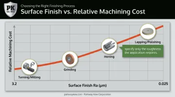
Surface finish capability is tied directly to the process producing it. As-machined turning or milling gets you into the 1.6-3.2 µm Ra range without extra steps. Getting tighter than that means adding operations: grinding, honing, lapping, or polishing, each with its own cycle time and cost.
Here's how that breaks down across common processes:
| Process | Typical Ra (µm) |
|---|---|
| Turning/Milling | 1.6-3.2 |
| Grinding | 0.4-1.6 |
| Honing | 0.1-0.8 |
| Lapping/Polishing | 0.025-0.4 |
That relationship runs in both directions. A rougher spec generally costs less; a smoother one generally costs more in machine time, inspection, and scrap risk.
Practical guidance: specify the roughest finish your application can tolerate, not the smoothest one available on the chart. Over-specifying a mirror finish adds:
- Adds extra machining or polishing passes
- Extends lead times on the shop floor
- Increases inspection costs
- Raises scrap risk on brittle or coated materials
Shops with in-house grinding skip part of this cost stack for mid-range specs. Parkway-Kew grinds up to 65 inches in diameter, so tightening Ra during the Restore & Grind process doesn't require outsourcing a separate step.
In practice, a sealing face or bearing journal might genuinely need 0.4 µm Ra or better. A mounting boss or non-functional surface almost never does. Matching the spec to the function, instead of defaulting to the tightest available number, is where real savings show up on a purchase order.
Why Surface Finish Matters in Heavy-Duty Industrial Applications
Surface finish isn't cosmetic. It drives friction, fatigue strength, corrosion resistance, and sealing performance in components under constant motion or repeated loading.
- Friction: larger surface asperities correlate with higher local friction in metal-forming contact, per NIST testing on sheet materials.
- Fatigue: surface roughness can meaningfully cut fatigue life. NASA testing on additively manufactured Inconel 718 found roughly a 0.33 fatigue-strength knockdown factor for as-built versus ground surfaces at lives under one million cycles.
- Corrosion: rougher surfaces show measurably higher corrosion current and lower polarization resistance in saltwater testing.
- Sealing: mating-surface roughness and lay direction directly affect leak paths in metal seals and rotating shaft seals.
Wire Drawing Blocks: Where Finish Transfers Straight to the Product
Few applications make the stakes more obvious than wire drawing. A block or capstan's surface finish doesn't just affect the block; it transfers directly onto the wire wrapping around it.
A worn, pitted, or inconsistent block finish shows up as scoring, marking, or breaks in the finished wire, often stopping the line.
This is the problem Parkway-Kew has built its coating technologies around since 1952. Its HVOF, plasma spray, thermal spray, and sub-arc hardsurfacing processes each suit different finish and wear demands:
- PK-400 metallizing targets surface-sensitive applications, providing the highest-quality finish to the wire itself. It's the standard choice for very large wire, where finish quality outweighs raw wear resistance.
- PK-200 sub-arc welding deposits a virtually crack-free surface, used when the characteristic heat-checked cracking of harder alloys like PK-503 would mark the wire.
- PK-920, PK-675, PK-700, and PK-750 HVOF coatings form dense, largely defect-free surfaces thanks to spray speeds exceeding Mach 2.
- PK-1500 chrome oxide plasma spray targets high-speed, high-slip ferrous wire drawing, where both wear resistance and finish quality matter.
When a block's drawline wears down, Parkway-Kew's Restore & Grind process fills and blends just that worn zone rather than grinding the entire block down to the deepest groove.
Because coatings go on at extra thickness from the start, a block can typically go through five to seven of these targeted repairs before a full recoat is needed, keeping the original finish intact across the rest of the surface.
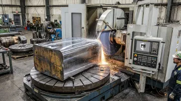
For blocks and capstans up to 65 inches in diameter and 12 feet long, that finish work happens on in-house CNC grinding equipment, so diameter, roundness, and surface consistency stay under one roof instead of shipping between vendors.
Frequently Asked Questions
What does surface finish mean?
Surface finish describes the texture of a surface, made up of roughness, waviness, and lay. In the US, it's governed by ASME B46.1 and shown on drawings per ASME Y14.36.
What is a 3.2 Ra surface finish?
A 3.2 µm Ra callout is a common as-machined standard finish with light, visible tool marks. It's a cost-effective baseline used widely in CNC machining before any secondary finishing.
What is Ra and Rz in surface finish?
Ra is the average deviation of the roughness profile from the centerline. Rz is the average of the five largest peak-to-valley deviations, making it more sensitive to isolated defects.
How is surface roughness measured?
Contact profilometers use a stylus to trace the surface and record a profile. Non-contact optical or laser methods scan without touching, which suits soft, coated, or delicate surfaces.
What is considered a good surface finish for industrial parts?
There's no universal answer; it depends on the application. The best practice is specifying the roughest finish that still meets the functional requirement, since tighter finishes add cost.
Why does surface finish matter for wear-resistant components like wire drawing blocks?
A block's finish transfers directly onto the wire being drawn. Poor or inconsistent finish causes wire defects and downtime, which is why specialized hardsurfacing and finish-matched alloys matter.