Many designers don't discover the physical limits of cutting tools and workholding until a quote lands on their desk or a batch of parts gets rejected at inspection. That's usually a design problem, not a machining problem.
This guide covers the design rules, material choices, and cost-reduction strategies that actually move the needle, whether you're machining a small precision bracket or a component that spans several feet.
Key Takeaways
- Respecting tool geometry limits (fillet radius, wall thickness, hole depth) is the biggest lever for controlling CNC cost and lead time.
- Over-tolerancing non-critical features is the most avoidable cost driver in a CNC quote.
- Material choice affects machinability, strength, and price at once, so pick based on function, not familiarity.
- CNC machining scales from micro-precision prototypes to multi-foot industrial parts, though few shops handle both ends.
What Is CNC Machining? A Quick Primer
CNC (Computer Numerical Control) machining is a subtractive process. A cutting tool removes material from a solid block of metal or plastic to reveal the final part. That puts it in a different category from additive processes like 3D printing, which build parts up layer by layer, and formative processes like injection molding, which shape material inside a die.
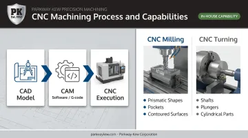
The basic workflow looks like this:
- A CAD model defines the part geometry.
- CAM software converts that model into toolpaths and generates G-code.
- The CNC machine executes the code, cutting, drilling, and finishing the part with minimal manual intervention.
Two core machine types dominate the shop floor:
- CNC milling: a rotating cutting tool moves against a fixed or repositioned workpiece. Ideal for prismatic shapes, pockets, and flat or contoured surfaces.
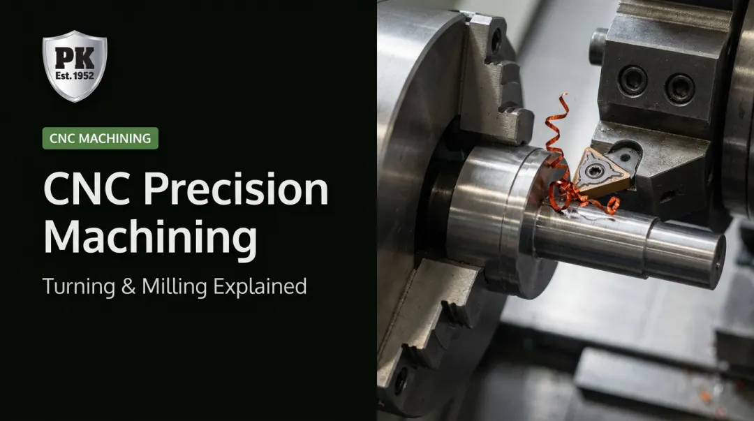
- CNC turning: the workpiece rotates against a stationary single-point tool. Best suited to cylindrical and rotationally symmetric parts like shafts and plungers.
Multi-axis machines combine both motions for complex geometries that need features cut from multiple angles in a single setup.
Design Guidelines & Best Practices for CNC Machining
Most "design for manufacturability" problems trace back to the same handful of physical restrictions: cutting tools are cylindrical, they need clearance to reach a feature, and thin material flexes under cutting force. Design around those three realities and most cost surprises disappear.
Fillets and Internal Corners
A rotating cylindrical tool physically cannot cut a perfectly sharp internal vertical corner. It will always leave a radius equal to the tool's own radius, no matter how the toolpath is programmed.
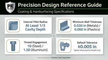
A common rule of thumb: specify an internal corner radius of at least one-third the cavity depth (Hubs' guide to sharp corners in CNC machining). This lets the machinist use a larger, stiffer cutting tool instead of a thin one that's prone to chatter and deflection.
- Maximize corner radii everywhere they're not functionally required to be sharp.
- True sharp corners are achievable with EDM (electrical discharge machining) or an added relief cut, but both add a secondary process and cost.
- Match radii to standard tool sizes rather than specifying odd dimensions.
Wall Thickness
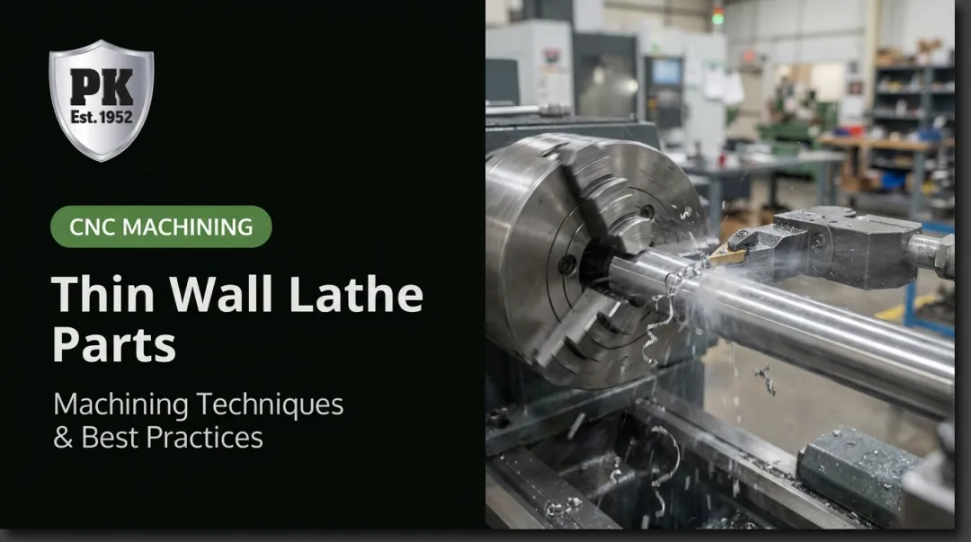
Thin walls vibrate, deflect, and warp during cutting. Once a wall gets too thin relative to its height, the tool starts pushing the material around instead of cutting it cleanly.
A widely cited industry benchmark recommends a minimum wall thickness of 0.030 inches (about 0.75 mm) for metals and 0.060 inches (about 1.5 mm) for plastics (Machine Design's CNC best practices guide). Treat these as dated design guidance, not a hard universal limit — actual survivability also depends on unsupported height, fixturing, and part size.
Plastics need thicker walls than metals for two reasons:
- Lower stiffness makes them more prone to deflection under cutting loads.
- Heat sensitivity means thin plastic sections can warp from the temperature generated during the cut.
Holes, Threads & Tapped Features
Stick to standard drill bit diameters whenever a hole doesn't need a specific bore size. Custom diameters require a boring operation instead of a simple drill cycle, which adds time.
One detail that trips up a lot of designers: a blind hole cut with a standard twist drill has a conical bottom, not a flat one. Common drill point angles run 118 to 135 degrees. If a flat-bottomed blind hole is functionally required, it needs to be called out explicitly, since it requires a different tool and an extra step.
For threaded holes:
- Steel threads typically need about 1D of engagement (one thread diameter's worth of depth), while aluminum threads generally need closer to 1.5D, since aluminum is softer (Fastenal's screw thread design reference).
- These are starting points, not universal rules. Final engagement should be verified against the actual mating thread strength.
- Larger thread sizes machine faster and cheaper than small ones, since bigger taps and drills are more rigid and tolerate higher cutting speeds.
Pockets, Cavities & Undercuts
Deep, narrow pockets are one of the fastest ways to inflate a machining quote. A long, skinny tool deflects, chatters, and struggles to clear chips out of the cavity.
- A common guideline caps pocket depth at roughly four times the pocket width.
- Tool reach varies by material — deeper cuts are achievable in aluminum than in steel because aluminum generates less cutting resistance.
- Undercuts need specialty tooling: T-slot cutters, dovetail cutters, or lollipop-shaped end mills that reach under an overhang. Keep undercut width reasonable relative to depth, and avoid them entirely where they're not functionally necessary.
Tolerancing Best Practices
One common shop default when no tolerance is specified is ±0.005 inches (0.13 mm) on machined dimensions. That said, this isn't a universal ISO standard — ISO 2768-1 tolerance classes actually vary by nominal dimension size, so a large part and a small one won't carry the same default tolerance.
Tighter tolerances can more than double the cost of a part through added fixturing, slower cycle times, and increased inspection time.
The fix is simple: reserve tight tolerances for features that are functionally critical, like a bearing bore or a mating surface, and leave everything else at the standard default. Blanket over-tolerancing across an entire drawing is one of the most common — and most avoidable — cost drivers we see. It's the same discipline our in-house grinding team applies during Parkway-Kew's Restore & Grind process, holding tight tolerances only on the wear surfaces that actually need them.
Choosing the Right Material for CNC Machined Parts
Material choice affects machinability, mechanical performance, tool wear, and part cost all at once. Pick the wrong one and you can end up paying a premium for strength you don't need, or worse, a part that fails in service.
Common CNC metals:
- 6061 aluminum — excellent machinability, good strength-to-weight ratio, and solid corrosion resistance. The default choice for general-purpose parts.
- 4140 alloy steel — high fatigue and impact strength, but machinability drops as hardness increases from heat treatment.
- Stainless steel — strong corrosion and oxidation resistance, but it work-hardens and conducts heat poorly, which accelerates tool wear.
Common CNC plastics:
- ABS — low cost, easy to machine, good for structural prototypes and housings.
- Nylon 6/6 — wear-resistant and strong, but absorbs moisture and can shift dimensionally as a result.
- Delrin/POM — excellent machinability and dimensional stability, a go-to for precision fittings and moving parts.
- PEEK — high-temperature and chemical resistance for demanding medical or industrial environments, at a higher material cost.
The general rule: choose the lowest-cost material that still meets the functional requirement. Don't default to a premium alloy or engineering plastic just because it's familiar.
Choosing the material is only part of the equation, though. Post-machining coatings and hardsurfacing can extend a component's service life without upgrading the underlying metal.
Parkway-Kew has applied this approach for over 70 years, coating machined parts with tungsten carbide, chrome oxide ceramic, and nickel chrome alloys to withstand heavy abrasion, from fracking plungers to wire drawing blocks.
For parts facing years of repeated wear cycles, a coated mid-grade base material often outperforms an expensive solid alloy on both cost and lifespan.
Cost-Saving Design Tips for CNC Machining
Beyond the feature-level rules above, a few broader design habits consistently reduce cost across an entire part or product line.
- Simplify geometry and minimize setups. Fewer repositions mean less manual handling and fewer chances for alignment error, so design parts to run in as few orientations as possible.
- Standardize fillet radii and hole sizes. Using the same radius and hole diameter across a design (or across a whole product family) cuts down on tool changes and programming time.
- Match tolerances and materials to actual function. Don't over-engineer specs "just in case": parts specified for the job they actually do, not a worst-case scenario that never happens, consistently quote lower.
These aren't complicated changes. They just require designing with the machinist's constraints in mind from the start, rather than fixing the drawing after the first quote comes back high.
Shops running in-house CNC machining and grinding, like Parkway-Kew, see this play out daily: parts designed around the process quote faster and run smoother on the floor.
Applications: From Precision Prototypes to Heavy-Duty Industrial Parts
CNC machining scales in a way few other processes do. The same underlying technology cuts a tiny electronics bracket and a six-foot-diameter industrial component — but not every shop is equipped to do both.
Small precision parts dominate electronics, medical devices, and rapid prototyping, where tolerances are tight and part sizes are measured in inches or millimeters. Heavy industrial sectors run on an entirely different scale.
Industries like oil & gas, wire mills, and shipping terminal operations routinely need large-format turning, milling, and grinding capacity that goes far beyond what a typical desktop-prototyping shop can offer:
- Fracking pump plungers that need precision-ground surfaces after coating.
- Wire drawing blocks and capstans, often 20+ inches in diameter.
- Crane wheels and wire rope pulleys used in shipping terminal operations.
Meeting these demands requires more than typical prototyping equipment. Parkway-Kew Corporation operates in-house CNC milling, CNC turning, and manual turning up to 72 inches in diameter, plus large-diameter grinding up to 65 inches in diameter and 12 feet in length.
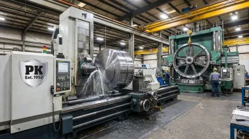
That capacity is paired with a proprietary Restore & Grind process that targets only the worn drawline area of a wire drawing block instead of regrinding the entire surface. The process extends usable life across five to seven repair cycles before a full re-coat is needed.
If you're designing an oversized or high-wear component, vet potential machining partners specifically for large-format capacity and hardsurfacing expertise. General CNC prototyping capability doesn't necessarily translate to handling a 12-foot shaft or a heavily worn capstan.
Frequently Asked Questions
Which machine tool is known as the "mother of all machine tools"?
The lathe is most often credited with this title. Britannica specifically calls it the "father of all other machine tools" since many of its mechanical elements were later incorporated into mills, drills, and other machine tools (Britannica's entry on the engine lathe).
What is the standard tolerance for CNC machined parts?
A common shop default is ±0.005 inches (0.13 mm) when no tolerance is called out. Tighter tolerances are achievable, but they can more than double the cost through added fixturing, slower cycles, and inspection time.
What is the minimum recommended wall thickness for CNC machining?
A widely used benchmark is 0.030 inches for metals and 0.060 inches for plastics. Plastics need thicker walls because they're more prone to heat-related warping and have lower stiffness under cutting loads.
How can I reduce the cost of my CNC machined parts?
Simplify geometry to reduce setups, standardize fillet radii and hole sizes across the design, and only tighten tolerances or upgrade materials where they're functionally necessary. These three levers account for most of the cost variation in a typical quote.
What's the difference between CNC milling and CNC turning?
Milling uses a rotating tool against a fixed or repositioned workpiece and suits flat, contoured, or pocketed geometries. Turning rotates the workpiece against a stationary tool and is best for cylindrical parts like shafts and plungers.
Can CNC machining produce large industrial parts, not just small prototypes?
Yes. Large-format CNC turning, milling, and grinding exist specifically for oversized components. Parkway-Kew, for example, machines parts up to 72 inches in diameter and grinds components up to 65 inches in diameter and 12 feet long.