Introduction
In arc welding, the filler metal decides more than most fabricators realize. Get it right, and a joint outlasts the equipment around it. Get it wrong, and you're looking at cracking, poor fusion, or corrosion that surfaces months after the job gets signed off.
The stakes are real. According to AWS's November 2025 repair guidance, a botched repair can turn a $5 consumable part into the reason a $50,000 asset gets pulled from service. In oil-and-gas piping, a failed weld typically means a full cutout, not a quick patch.
Filler metal selection touches base metal chemistry, welding process, joint position, mechanical demands, and environmental exposure all at once. This guide breaks down what actually matters, from standard shop fabrication through heavy-wear industrial rebuilds.
Key Takeaways
- Filler metal is added during arc welding to fuse two base metals into one joint
- Selection depends on base metal type, welding process, joint design, and environment
- The right choice boosts joint strength and wear resistance while cutting rework costs
- Heavy-wear industrial parts often need hardfacing alloys that standard fillers can't match
What is a Filler Metal in Arc Welding?
A filler metal is the metal alloy added to a joint during arc welding. It melts into the arc, mixes with the base metal, and solidifies to form the finished weld. Without it, most arc welding joints would never gain enough strength to hold.
Filler metal reaches the joint one of two ways:
- Consumable electrodes or wire: Used in SMAW (Shielded Metal Arc Welding), GMAW (Gas Metal Arc Welding), and FCAW (Flux-Cored Arc Welding), where the electrode itself melts and becomes part of the weld
- Separately-fed filler rod: Used in GTAW (Gas Tungsten Arc Welding), where a non-consumable tungsten electrode creates the arc while a rod is fed in by hand
The delivery method shapes everything downstream, from deposition speed to how much control the welder has over the puddle.
Types of Filler Metals Used in Arc Welding
Each arc welding process pairs with its own filler format, and picking the right one changes weld speed, appearance, and where the job can happen.
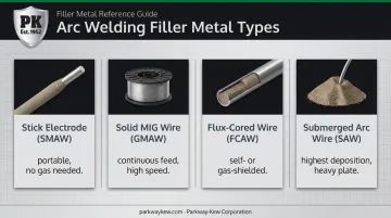
Covered/Stick Electrodes (SMAW)
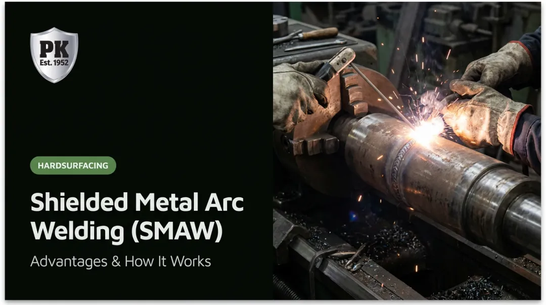
Stick electrodes are solid metal rods wrapped in a flux coating. The coating shields the molten weld pool from the atmosphere, stabilizes the arc, and sometimes adds alloying elements to the deposit. Cellulosic coatings favor deep penetration and vertical-down welding, while basic, low-hydrogen coatings suit jobs needing high tensile strength and impact toughness.
Stick welding travels well and needs no external gas. That's why it stays the go-to choice for field repair, maintenance, and general fabrication where portability matters more than raw speed.
Solid MIG Wire (GMAW)
GMAW feeds a continuous solid wire electrode through a gun while shielding gas protects the weld pool. For mild steel, ER70S-6 is common where extra deoxidizers are needed to handle mill scale or rust, while ER70S-3 covers cleaner base metal.
This process is built for speed. It's the standard for high-volume production welding on mild steel and stainless in shops where shielding gas coverage is easy to maintain.
Flux-Cored Wire (FCAW)
FCAW uses tubular wire filled with flux. Self-shielded (FCAW-S) versions generate their own shielding from the core ingredients, making them ideal for outdoor or windy job sites where gas shielding would simply blow away. Gas-shielded (FCAW-G) versions need external shielding, commonly 100% CO2 or a 75-85% argon/CO2 blend.
Both variants handle thicker sections at higher deposition rates than stick electrodes, which is why FCAW shows up often in structural and heavy fabrication work.
Submerged Arc Wire & Hardfacing Electrodes (SAW)
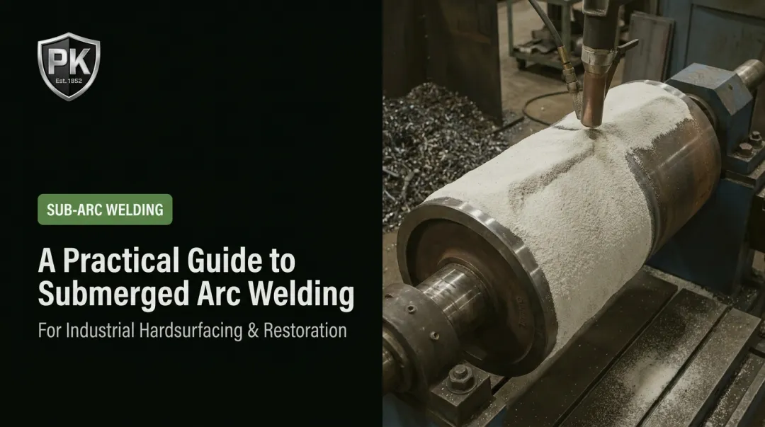
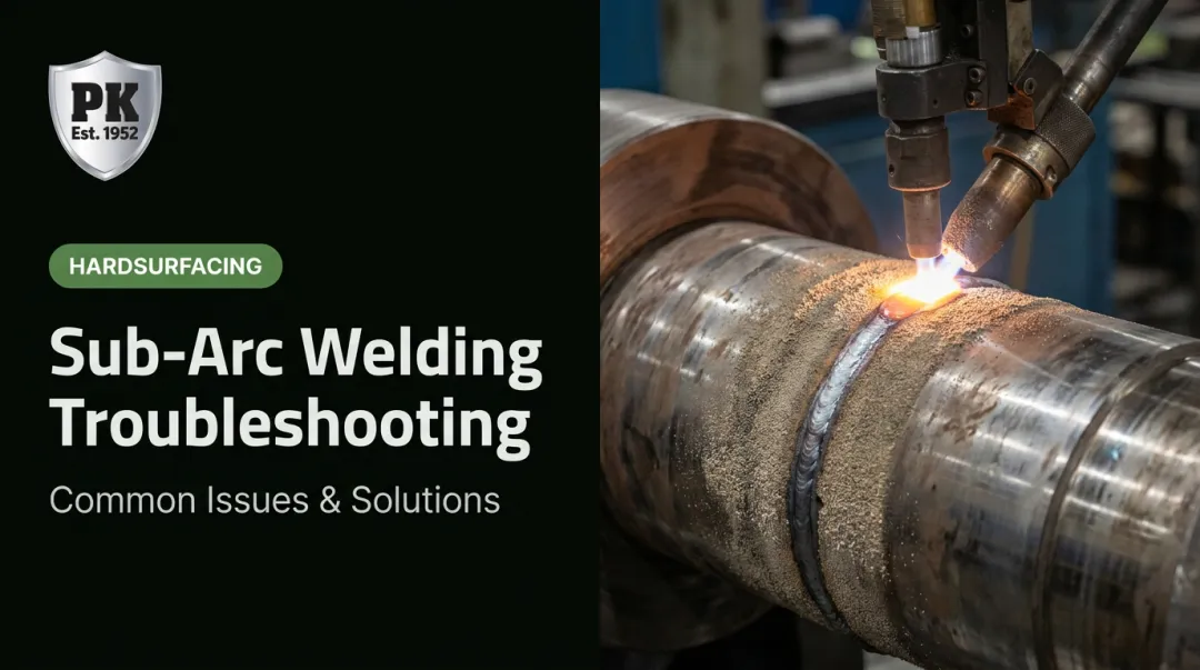
SAW pairs a continuous wire electrode with a blanket of granular flux that fully covers the arc. That combination allows very high deposition rates and clean, spatter-free welds, making it a longtime favorite for heavy-plate fabrication and rebuild work.
Parkway-Kew pioneered this exact application back in the 1950s, adapting SAW specifically for rebuilding and hardsurfacing wear components like wire drawing blocks. That wasn't a generic use of the process. It required developing proprietary alloys formulated for extreme surface hardness rather than standard structural strength.
Benefits of Choosing the Right Filler Metal
Picking the correct filler metal pays off in ways that show up directly on the shop floor and the balance sheet:
- Stronger metallurgical bonds that resist cracking under load or thermal cycling
- Better corrosion and wear resistance, extending service life in harsh environments
- Consistent weld appearance and bead profile, reducing inspection callbacks
- Fewer part replacements, since properly matched filler doesn't fail prematurely
- Lower total cost of ownership, even when the correct filler costs more upfront
The trade-offs between fillers are real and well documented. ESAB's comparison of 4043 and 5356 aluminum filler alloys shows 4043, at roughly 5% silicon, delivers transverse shear strength around 15 ksi, while 5356, at roughly 5% magnesium, reaches about 26 ksi.
Same base metal, same process, very different mechanical outcome depending on filler choice alone.
Filler metal selection deserves the same engineering scrutiny as base metal selection, not a last-minute purchase decision based on price alone.
What to Consider When Choosing the Best Filler Metal for Arc Welding
Filler metal selection isn't one-size-fits-all. It shifts based on base metal, industry application, and the environment a part will live in. The following factors turn technical specifications into outcomes you can measure on the production floor.
Base Metal Compatibility
The filler's chemical and mechanical properties need to closely match, or intentionally complement, the base metal. Get this wrong and you risk cracking or galvanic corrosion right at the joint.
Hobart's technical guidance gives a clear example: ASTM A387 Grade P11 chrome-moly pipe requires a filler with roughly 1.25% chromium and 0.5% molybdenum to match. Shops typically pair A36 steel, rated at a 36 ksi minimum yield strength, with a 70 ksi tensile-class filler. When the original filler used in a repair is unknown, chemical analysis of the existing weld beats guessing every time.
Mismatched filler remains a leading cause of weld failure and warranty claims across fabrication shops.
Welding Process Selection
Each arc welding process demands filler in a different form: rod, wire, or coated electrode. That choice affects deposition rate directly. SMAW loses efficiency to stub ends and slag. Continuous-feed processes like GMAW and FCAW cut those losses and push deposition higher, while SAW pushes further still using flux and wire together.
The correct process-and-filler pairing changes welding speed, which changes labor cost per joint. Settle on your process before locking in filler diameter or alloy.
Joint Design and Welding Position
Joint geometry (fillet, butt, groove) and welding position (flat, vertical, overhead) both dictate filler diameter and viscosity. Industry guidance generally treats 3/16 inch as the largest practical SMAW electrode size for vertical and overhead welding, while low-hydrogen electrodes top out closer to 5/32 inch in the same positions.
Ignore this and defect rates climb. A filler that runs beautifully flat can sag, undercut, or trap slag overhead. Match filler to position before the first pass, not after an inspector flags the joint.
Mechanical Property Requirements
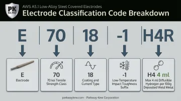
Tensile strength, ductility, and impact toughness requirements, especially on structural or load-bearing parts, determine which filler alloy grade you need. Take E7018-1 H4R as an example:
- 70 denotes a 70 ksi tensile class
- -1 suffix adds low-temperature impact requirements
- H4 guarantees less than 4 ml of diffusible hydrogen per 100g of deposited weld metal
Undersized mechanical properties don't just look bad on paper. They shorten service life and shrink the safety margin on parts that can't afford to fail.
Wear, Corrosion, and Environmental Resistance
Parts exposed to abrasion, impact, or corrosive conditions, common across oil and gas, mining, and heavy equipment, need specialized hardfacing or alloy fillers rather than standard options. A standard mild steel filler won't survive repeated abrasive contact for long.
The evidence backs this up. ESAB documented a case where switching to Stoody 160FC hardfacing wire doubled the service life of a heavily worn recycling press screw. Choosing the correctly rated wear-resistant filler alloy directly reduces how often parts get changed out and how much unplanned downtime a facility absorbs.
When welded hardfacing wears too fast or doesn't fit the part's geometry, thermal spray coatings offer another route. Parkway-Kew Corporation applies HVOF and plasma spray coatings to fracking plungers and wire drawing blocks for exactly this reason.
Shielding Gas Compatibility, Storage, and Handling
Filler wire performance in GMAW and FCAW depends on pairing it with the correct shielding gas. FCAW-G wires need their classified gas, commonly 100% CO2 or a 75-85% argon/CO2 blend, while FCAW-S needs none at all.
Storage matters just as much. Moisture-contaminated consumables directly cause porosity and hydrogen-induced cracking. Higher-strength electrodes like E8018 should get no more than three one-hour re-dries at 700-800°F. Poor storage and handling remain a common root cause of the porosity and cracking defects inspectors find in the field.
How Parkway-Kew Can Help
When standard filler metals aren't enough to withstand extreme wear, corrosion, or heavy cyclical loads, that's where Parkway-Kew's hardsurfacing expertise comes in.
Since the 1950s, Parkway-Kew has specialized in exactly this problem. The company pioneered submerged arc welding for rebuilding and hardsurfacing wear components, starting with a landmark order to rebuild 100 wire drawing blocks for CF&I in Roebling, NJ. That project proved hardfacing alloys, once used mainly to repair earth-moving equipment, could be adapted into precision-grade wear solutions.
The company kept building on that foundation. Parkway-Kew introduced the first HVOF coating for wire drawing blocks in 1989 and added plasma spray ceramic coatings in the late 1990s. More recently, it developed the proprietary Restore & Grind process, which targets only the worn drawline area of a block instead of grinding down the entire surface. That approach allows 5 to 7 lower-cost repairs before a full recoat is needed.
What sets the approach apart today:
- A full range of hardsurfacing options, including SAW, HVOF, thermal spray, and plasma spray, matched to the wear, corrosion, or surface-finish demands of each part
- PK-730, a proprietary fused tungsten carbide coating built for the harshest fracking plunger applications, where standard nickel-chrome coatings wear out fast
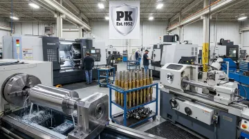
- In-house CNC machining up to 72 inches and grinding up to 65 inches in diameter, so coated components get finished to precise tolerances under one roof
For a fabricator wrestling with a component that keeps failing under abrasive wear or corrosive load, standard filler metal charts only go so far. Parkway-Kew's team can help identify the right wear-resistant alloy and hardfacing method for a specific rebuild. Reach the team at (732) 398-2100 or info@parkwaykew.com.
Conclusion
Choosing the right filler metal comes down to matching it with the base metal, the process, and the environment the finished part has to survive — not just grabbing the most familiar option off the shelf.
For routine fabrication, standard filler grades handle the job fine. But once a component faces heavy abrasion, corrosive exposure, or constant cyclical loading, specialized hardfacing alloys deliver far better long-term value than a general-purpose filler ever will.
Filler metal selection isn't a decision you make once and forget. Operating conditions shift, base materials get substituted, and failure patterns change. Review your filler choices periodically, especially after a part fails earlier than expected.
Frequently Asked Questions
What is a filler metal in welding?
A filler metal is the material added during welding that melts and combines with the base metal to form the finished joint. It's what fuses two separate pieces into one continuous weld.
What are the filler materials used in arc welding?
The main categories are covered electrodes (SMAW), solid wire (GMAW), flux-cored wire (FCAW), and filler rods (GTAW), plus wire-and-flux systems for SAW. Each falls under a different AWS specification depending on base metal and process.
What is the filler material used in gas welding?
Gas welding typically uses a bare filler rod with a composition close to the base metal, fed manually into the torch flame as it melts. AWS A5.2 covers carbon and low-alloy steel rods used for this process.
Are welds as strong as the base metal?
With the correct filler and proper technique, a weld can match or even exceed base metal strength. Industry guidance recommends filler that slightly overmatches the base metal so the weld isn't the weakest point.
How do I match filler metal to the base metal I'm welding?
Match filler based on chemical composition compatibility, checking AWS classification charts or the base alloy's manufacturer data sheet. When the original filler is unknown, a chemical analysis of the existing metal is the safest approach.
What happens if I use the wrong filler metal for a welding project?
Incorrect filler selection can cause cracking, poor fusion, corrosion, or premature failure, particularly under wear or load-bearing conditions. In heavy industrial settings, this often means unplanned downtime and costly part replacement.