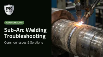
But SAW comes with a fundamental challenge: the arc and weld pool are completely hidden beneath a flux blanket. Problems that would be immediately visible in MIG or stick welding — a wandering arc, poor fusion, gas escaping the pool — go undetected until inspection reveals a defect. By then, the part may already be scrapped or require costly rework.
This guide covers the four primary SAW defects — porosity, lack of fusion, slag inclusions, and weld cracking — with practical diagnosis steps and targeted fixes. It also covers when to handle repairs in-house and when to bring in a specialist.
Key Takeaways
- Porosity almost always traces to moisture-contaminated flux or dirty joint surfaces — fix the consumable before adjusting parameters
- Lack of fusion on circumferential welds is typically a weld head offset problem, not a heat input problem
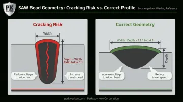
- Centerline cracking indicates a bead geometry issue: width-to-depth ratio must stay above 1:1
- Most SAW defects are preventable with disciplined flux handling, consistent joint prep, and operator training
- Persistent cracking on high-value components warrants professional intervention — not repeated trial-and-error
What Is Submerged Arc Welding?
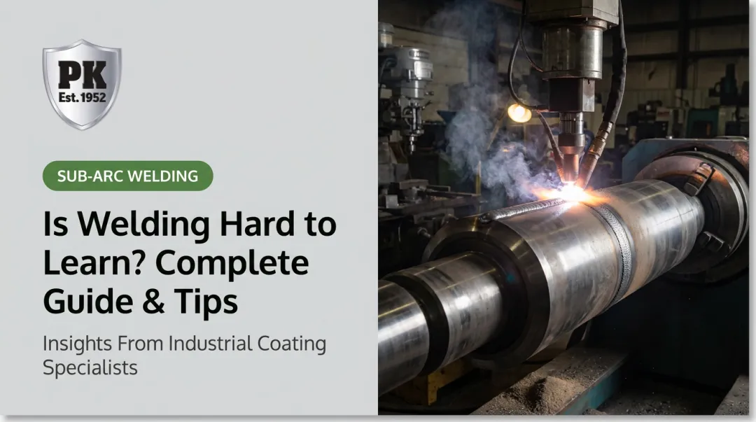
TWI defines submerged arc welding as an automatic or semi-automatic process in which an arc forms between a continuously fed bare wire electrode and the workpiece, with the arc and molten pool completely shielded under a blanket of granular fusible flux. There is no visible arc light. The operator cannot see the weld pool.
That flux blanket prevents atmospheric contamination, enables deep penetration, and supports very high deposition rates. It's also what makes troubleshooting difficult. Small deviations in flux condition, wire setup, CTWD, or joint cleanliness that would be caught immediately in open-arc welding go unnoticed until a defect surfaces during inspection.
Where SAW Gets Used
SAW is well-suited for flat and horizontal welds on thick materials. Common applications include:
- Structural and bridge fabrication
- Pressure vessels and offshore structures
- Pipe welding and shipbuilding
- Hardsurfacing and rebuilding of heavy industrial components
That last application has a long commercial history. Parkway-Kew Corporation pioneered the use of sub-arc welding for hardsurfacing and rebuilding wire drawing blocks in the 1950s — starting with an order to rebuild 100 Vaughn wire drawing blocks for CF&I in Roebling, NJ. Sub-arc remains the company's premier method for this application today, using proprietary alloys PK-503 (a super-hard alloy with characteristic heat-check cracking) and PK-200 (same hardness, virtually crack-free deposit for sensitive wire applications).
Common Sub-Arc Welding Problems: Symptoms and Causes
SAW defects follow recognizable patterns. Since operators can't see the arc or weld pool directly, matching symptoms to root causes is where troubleshooting starts.
Porosity
Gas pockets appear on the bead surface or through NDT — scattered or clustered voids, often near the weld centerline or on the second-side pass.
Common causes:
- Moisture-contaminated flux (most common)
- Joint surface contamination — rust, oil, paint, or mill scale
- Electrode contamination from improper wire storage
- Insufficient flux coverage exposing the arc
- High travel speed causing fast solidification that traps gas
- Arc blow
- Sulfur segregation in free-machining steels
TWI's SAW porosity guidance specifically identifies joint surface contamination — oil, paint, grease, and hydrated oxides — as a primary cause. Miller Electric separately confirms that moisture-contaminated flux directly causes weld rejects.
Lack of Fusion (LOF)
Voids or unbonded zones appear between passes or between the weld and base metal, revealed by cut-and-etch or NDT. LOF often co-occurs with centerline porosity on the second side of double-sided welds.
Common causes:
- Weld parameters too low for the joint configuration
- Weld metal rolling ahead of the arc (common at too-slow travel speed in V-grooves)
- Incorrect weld head offset from top dead center (TDC) on circumferential welds
- Inconsistent root face dimensions causing variation between burn-through and cold lap
Slag Inclusions
Solid foreign material trapped in the weld deposit shows up through NDT. A razor-backed (centerline high) or concave bead profile typically points to an offset error.
Common causes:
- Insufficient travel speed allowing the weld pool to surge over the slag
- Improper weld head offset on circumferential welds
- Incomplete slag removal between passes on multipass welds
- Flux viscosity too high for the application
Weld Cracking (Centerline and HAZ)
Longitudinal centerline cracks run through the weld bead. HAZ cracks may not appear until hours or days after welding (delayed hydrogen cracking). Transverse cracks can also develop in high-strength weld deposits.
TWI's solidification cracking guidance identifies the primary drivers clearly:
Centerline cracking causes:
- High depth-to-width ratio (bead narrower than it is deep)
- Hat-shaped bead profile from excessively slow travel speed
- Carbon, sulfur, or phosphorus contamination in the base material
HAZ/cold cracking causes:
- Residual hydrogen from wet flux or insufficient preheat
- High carbon equivalent base material
- Excessive heat input or rapid cooling rate
TWI provides a Units of Crack Susceptibility (UCS) formula for SAW: UCS = 230C + 190S + 75P + 45Nb − 12.3Si − 5.4Mn − 1. A UCS below 10 indicates high cracking resistance; above 30 indicates low resistance. Values around 25 signal meaningful cracking risk in butt welds.
How to Troubleshoot and Fix SAW Issues
Isolate the defect type before changing any parameter. Adjusting the wrong variable wastes time and can introduce new problems. Increasing current to address porosity caused by wet flux, for example, does nothing except change your heat input.
Fixing Porosity
Work through these steps in order:
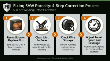
- Recondition or replace flux — Check for moisture exposure. Per ESAB's flux handling guidelines, rebake flux at 350°C ± 25°C for a minimum of 4 hours with flux depth not exceeding 50mm. Never use flux left in open hoppers overnight or over weekends.
- Clean joint surfaces — Grind or wire-brush all mating surfaces to remove rust, mill scale, oil, and primer before fitting. Apply the same standard used during procedure qualification to every production weld.
- Check wire storage — Inspect coils that have been on the feeder in humid conditions. Surface rust on the wire is a red flag; remove and replace.
- If porosity persists — Reduce travel speed to give gases more time to escape before the pool solidifies. Verify flux coverage depth and nozzle-to-work distance.
Fixing Lack of Fusion
For plate welds: Review heat input parameters and increase current or voltage if the joint configuration demands more energy. Verify travel speed isn't allowing the puddle to roll ahead of the arc, particularly in V-groove configurations.
Hold root face and gap dimensions to tight tolerances. Inconsistency between joint sections creates zones where burn-through alternates with cold lap.
For circumferential welds: Plate issues aside, circumferential welds introduce a different variable — weld head offset from TDC. Gravity affects how the molten pool behaves on a rotating cylindrical workpiece.
- Too little offset → weld metal rolls forward over the arc
- Too much offset → weld metal rolls backward
Molten flux spillage is a visible signal that the offset is wrong. Adjust the head position and re-evaluate the bead profile before continuing.
Fixing Slag Inclusions
- Increase travel speed (within acceptable limits) to prevent the weld pool from surging forward over the slag
- Remove all slag between passes on multipass welds — do not assume the arc will consume residual slag from previous beads
- Re-evaluate TDC offset if inclusions correlate consistently with circumferential welds
- Switch to a lower-viscosity flux if slag is repeatedly failing to float clear of the weld pool
Fixing Weld Cracking
For centerline cracks: The fix is bead geometry. Target a width-to-depth ratio of approximately 1.1:1 to 1.4:1. To get there:
- Increase voltage to widen the bead
- Increase travel speed to reduce depth
- Avoid hat-shaped profiles — a sign of excessive slow travel
- If base material contamination (sulfur, zinc, lead) is suspected, reduce penetration or use deoxidizer-rich flux and wire combinations
For HAZ/cold cracking: Hydrogen control is the priority.
- Determine required preheat based on the carbon equivalent of the base material and section thickness — consult a welding engineer if the CE value is unknown
- Use low-hydrogen flux, stored in heated cabinets
- Consider hydrogen-scavenging flux types for sensitive materials
Lincoln Electric notes that ultra-low hydrogen SAW flux typically delivers less than 3 mL/100g of deposited weld metal — a useful spec to reference when selecting consumables for crack-sensitive work.
When to Fix In-House vs. Call a Professional
Not every SAW problem should be solved with parameter tweaks. When defects recur despite correct procedures, or when the component has critical wear or dimensional requirements, the cost of repeated in-house attempts quickly exceeds the cost of professional intervention.
Handle In-House When:
- The defect traces directly to a single correctable variable (wet flux causing porosity, incorrect CTWD causing inconsistent penetration)
- The base material is standard structural steel
- The repair does not affect structural or wear performance of a critical component
Call a Professional When:
- Cracking recurs after implementing preheat and hydrogen control
- The component is subject to high-stress cycling, heavy wear, or precision dimensional requirements
- The application involves specialized hardsurfacing alloys where chemistry selection directly affects performance
Wire drawing blocks illustrate exactly when professional capability matters. Choosing between a super-hard alloy like PK-503 (which produces characteristic heat-check cracking) and a crack-free alternative like PK-200 requires deep experience in both the welding process and the downstream wire quality requirements — getting it wrong affects the wire itself, not just the block.
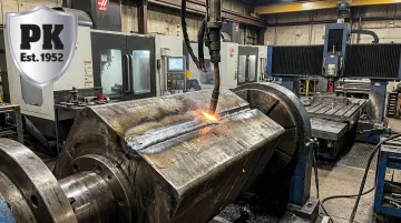
Parkway-Kew Corporation has been making that call since the 1950s. The process pairs sub-arc welding with in-house grinding up to 65" diameter and CNC machining up to 72" diameter, bringing rebuilt components back to precise final dimensions.
Preventive Measures and Common Mistakes to Avoid
Most SAW defects are preventable. Most recurring problems trace to three controllable failures: improper consumable handling, inadequate joint preparation, and undertrained operators.
Key Preventive Actions
Flux handling:
- Store sealed flux drums at 20°C ± 10°C with relative humidity below 70% (ESAB)
- Rebake exposed flux before use — 350°C for at least 4 hours
- When using flux recovery systems, add at least one part new flux to every three parts recovered flux (ESAB); screen for metallic particles and degraded fines before reuse
Joint preparation:
- Apply the same surface cleanliness standards used during procedure qualification to every production weld
- Clean, dry, dimensionally consistent joints are the single most controllable variable in SAW quality
Wire straightener and CTWD discipline:
- Set up the wire straightener correctly for every run — electrode wander causes inconsistent penetration and fusion
- Measure CTWD from the contact tip, not the flux nozzle
- Adjust the flux nozzle independently when changing coverage depth
Common Mistakes to Avoid
- Treating symptoms instead of root causes: slowing travel speed to mask porosity when wet flux is the actual problem
- Skipping interpass slag removal on multipass welds
- Assuming recovered flux is clean without screening and mixing with virgin flux
- Deploying undertrained operators: SAW operators may not come from manual welding backgrounds and may not recognize how arc-hidden parameters affect quality. Parameter awareness and procedural discipline replace visual feedback entirely in SAW
Frequently Asked Questions
What causes porosity in submerged arc welding?
Porosity in SAW is most commonly caused by moisture-contaminated flux, surface contamination on the joint (rust, oil, paint, mill scale), or electrode contamination from improper wire storage. High travel speed and arc blow are additional contributing factors, particularly when other variables are marginal.
How do I know if my SAW flux needs to be replaced or reconditioned?
Bake flux per manufacturer specifications if it has been exposed to humidity or left in open hoppers. Recovered flux with degraded particle size or metallic contamination should be partially replaced: blend at least one part new flux with every three parts recycled flux before use.
What is the correct width-to-depth ratio for a submerged arc weld bead?
The target width-to-depth ratio for SAW beads is approximately 1.1:1 to 1.4:1. Beads with a depth-to-width ratio greater than 1:1 (narrower than deep) are prone to centerline cracking due to solidification mechanics — segregating elements collect at the weld centerline as the bead solidifies inward from both sides.
Why does lack of fusion occur more on circumferential SAW welds?
On circumferential welds, gravity affects the pool based on bead position relative to top dead center. Incorrect weld head offset causes molten metal to roll forward or backward over the arc, preventing proper fusion and producing molten flux spillage or an irregular bead profile.
Can submerged arc welding be used for hardsurfacing and wear repair?
Yes. SAW is widely used for hardsurfacing and rebuilding worn components including wire drawing blocks, capstans, and heavy industrial parts. Alloy selection and process control are critical — the deposit chemistry directly determines wear resistance, surface integrity, and compatibility with the application.
When should I consider professional hardsurfacing instead of in-house SAW repair?
Professional hardsurfacing is the right call when the component has critical dimensional tolerances, requires specialized wear-resistant alloys, or when recurring defects indicate the in-house process can't achieve consistent results. High-cycle components like wire drawing blocks demand both process expertise and post-weld precision machining to meet dimensional specifications.