TIR (Total Indicator Reading, also called total indicator runout or full indicator movement) is one of those small numbers that quietly governs how true a rotating part runs about its axis. It's measured in thousandths of an inch, sometimes millionths, yet it drives tool life, surface finish, vibration, and how long a bearing, spindle, or wire drawing block lasts before it needs to come off the line.
Many manufacturers chase surface finish problems or premature tool wear for weeks before someone finally checks runout and finds the real culprit. This guide breaks down what TIR actually means, how it differs from runout and FIM, what a reasonable tolerance looks like, how to measure it correctly, and what happens when it drifts out of spec.
Key Takeaways
- TIR equals the max minus min indicator reading over one full 360° rotation about a datum axis
- Runout checks a single cross-section; TIR evaluates the entire specified surface
- Acceptable ranges span a few ten-thousandths on precision spindles to several thousandths on general shafting
- Measurement relies on dial/digital indicators with V-blocks, or CMM and CNC touch probes for automated checks
- Compounding runout across an assembly, not a single bad part, causes most premature tool and bearing failures
What Is TIR in Manufacturing?
In technical terms, TIR is the total lateral distance an indicator tip travels across the surface of a rotating part during one complete revolution about a reference axis.
Mitutoyo's own metrology guidance puts it plainly: runout value (TIR) = MAX − MIN, recorded as the part turns a full 360 degrees against a fixed indicator. Mitutoyo's Quick Guide to Precision Measuring Instruments confirms this is the standard calculation used across dial and digital indicator products.
On an engineering drawing, TIR shows up through the total-runout GD&T symbol (the double arrow), referenced to a datum axis. That callout creates a tolerance zone: every point on the specified surface has to fall inside it as the part rotates. So TIR does double duty: it serves as a design specification, a hard limit printed on the blueprint, and as an operating variable, a live health check performed on the shop floor or in the field.
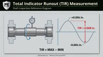
Here's the concept in plain numbers. If a shaft deviates +0.004 in. above true center at one point and -0.004 in. below at another, the TIR isn't 0.004 in.
It's 0.008 in., the full swing from max to min. That distinction trips people up constantly, and it's the source of a lot of "why did my part fail when it was supposedly in tolerance" conversations.
Factors That Influence TIR in Real-World Operation
Theoretical, as-designed TIR and as-measured TIR rarely match perfectly once a part leaves the drawing board. Several things pull them apart:
- Design and material limits - shaft stiffness, bearing quality, and material consistency all set a floor on how tight TIR can get
- Manufacturing variation - out-of-round or tapered blanks introduce runout before the part even sees its first duty cycle
- Operating conditions - load profiles, thermal growth, and duty cycle shift TIR while the machine is running versus sitting on a bench
- Compounding through the assembly - individual runout in each component stacks up: spindle, tool holder, and cutting tool; or bearing, shaft, and wire drawing block
One nuance worth flagging: compounding doesn't always add up the worst-case way. Misalignments can partially cancel each other out depending on orientation. That's exactly why a single component's nominal TIR rating doesn't guarantee assembly-level performance.
Range of TIR: Nominal Values, Tolerances, and Safe Operating Margins
There's no universal "good" TIR number. Acceptable TIR depends on the component's design limits, its application, and how hard it's being run.
Nominal Operating Range
Published values vary enormously by component type:
| Application | Typical TIR/runout value |
|---|---|
| Precision machine-tool spindle interfaces | Tenths of a thousandth (a few micrometers) |
| General rotating shafting/equipment | A few thousandths of an inch |
| Rotating drilling setups | Should not exceed 20 micrometers, per Sandvik Coromant's drilling guidance |
| Large-diameter industrial components (wire drawing blocks, capstans) | Held tight to prevent wire scoring and vibration |
These figures assume a clean assembly, a machine at operating temperature, and correct mounting. Change any of those assumptions, and the real-world number moves.
Allowable Tolerance and Boundary Limits
Nominal ranges show what's typical, but they aren't the final word. Upper and lower limits get set on the drawing itself, through the total-runout symbol and its datum reference, and that callout is the authoritative source, not a rule of thumb from a forum post.
Two distinct situations apply here, and confusing them causes problems:
- Short-term acceptable deviation - some runout during break-in is normal and self-corrects as components seat
- Continuous-duty limits - sustained runout above the design tolerance signals it's time for maintenance or a rebuild, not a wait-and-see approach
Safe Operating Margin
Smart operators don't run right up to the printed limit. They build in margin, because a part sitting exactly at its boundary has zero room left to absorb the runout that naturally accumulates from wear over time.
Pushing a component too close to the limit creates:
- Accelerated wear on the affected surface
- Reduced capacity to tolerate additional compounding runout before failure
- Higher odds of an unplanned shutdown instead of a scheduled one
For large rotating components like wire drawing blocks and capstans, this is where precision resurfacing earns its keep. Rather than scrapping a worn block once it drifts out of tolerance, Parkway-Kew's CNC grinding and Restore & Grind process brings the drawline area back within tight TIR tolerances.
The process fills and blends only the worn section, instead of regrinding the entire surface down to the deepest groove. That approach preserves usable coating and typically allows 5 to 7 repair cycles before a full recoat is needed.
How TIR Is Specified, Measured, and Validated
TIR lives in two worlds: it's a design specification printed on a drawing, and it's an operational check performed on the shop floor.
Specification and Documentation
Engineering drawings and datasheets specify TIR through the total-runout GD&T symbol, tied to a datum axis. Two versions matter here: rated/nominal TIR is the design intent printed on the drawing, while as-tested/as-measured TIR is what's actually recorded during inspection, which can differ from nominal even on a good part.
Measurement and Verification Methods
The classic approach still works fine for most shop-floor needs:
- Mount the part on V-blocks or between centers
- Position a dial or digital indicator against the surface being checked
- Rotate the part a full 360°, watching for max and min readings
- Calculate TIR as max minus min (many digital indicators do this automatically)
For higher-precision or automated needs, shops step up to:
- CNC/CMM touch-probe digitizing for surface mapping and automated compensation
- Auto-presetters for tool and holder verification before parts ever hit the spindle
- Master or test bar checks to verify spindle and assembly TIR against a known artifact
One detail that trips people up: field measurement, taken in-machine at operating temperature, doesn't always match lab or bench measurement taken cold. Thermal growth and load shift the numbers, so a part that passes on the bench isn't automatically guaranteed to hold that same TIR once it's running hot under load.
Implications of Excessive TIR and Common Misinterpretations
Excessive TIR directly reduces performance and shortens part life - it's never just a cosmetic issue.
The performance losses show up as:
- Uneven chip load on cutting tools, since only part of the tool engages the material at any given moment
- Poor surface finish, from inconsistent contact between tool and workpiece
- Vibration and chatter, which compounds wear on everything downstream
Left unaddressed, these mechanisms turn into failure modes:
- Premature tool or bearing wear, sometimes concentrated on a single flute of a multi-flute tool until it wears down faster than the rest
- Oversized holes in drilling operations, because the drill rotates off-axis
- Reduced service life on rotating components generally
BIG DAISHOWA reported that improving runout from 0.0006 in. to 0.00008 in. tripled the life of a solid-carbide tool - the difference between changing tools once a shift versus once every three.
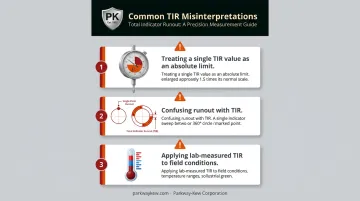
Three misinterpretations keep causing avoidable problems:
- Treating a single nominal TIR value as an absolute pass/fail limit without accounting for compounding through the full assembly
- Confusing runout with TIR: checking one cross-section when the specification actually calls for evaluating the entire surface
- Applying lab-measured TIR directly to field conditions without adjusting for thermal growth or operating load
Conclusion
TIR functions as a governing parameter, tied directly to tool life, surface finish, and how long a piece of rotating equipment stays in service. Understanding acceptable ranges and measuring correctly matters just as much as knowing the published tolerance number itself.
For high-wear rotating components like wire drawing blocks and capstans, keeping TIR in check over years of service requires ongoing maintenance rather than a one-time fix.
Parkway-Kew has spent decades helping wire mills and industrial operators restore worn components to tight TIR tolerances through precision coating and grinding, rather than replacing parts that still have useful life left.
Frequently Asked Questions
What is TIR in machining?
TIR is the maximum-minus-minimum indicator reading recorded as a rotating part completes one full turn about its axis. In machining, it directly affects tool wear, chip load, and surface finish quality.
What's the difference between runout and TIR?
Runout applies to a single cross-section or location on a part. TIR, also called total runout, evaluates the entire specified surface across a complete 360° rotation.
What is an acceptable TIR tolerance in manufacturing?
It depends on the application, ranging from a few micrometers on precision spindles to several thousandths on general shafting. The engineering drawing's datum callout is the authoritative source, not a general rule.
How is TIR measured?
Most shops use a dial or digital indicator with V-blocks, rotating the part a full 360° and recording max and min readings. Higher-precision needs call for CMM touch probes, auto-presetters, or master test bars.
What is FIM (Full Indicator Movement)?
FIM is another term used alongside TIR to describe the same max-minus-min indicator span during a full rotation. The two terms are used interchangeably in shop-floor practice.
What causes excessive TIR in a machine or part?
Common causes include compounding runout through an assembly (spindle, holder, and tool, or bearing, shaft, and block), manufacturing defects like out-of-round stock, accumulated wear, and improper mounting or misalignment.