Introduction
Carbon steel carries the load in process piping, pressure vessels, and heavy equipment across oil and gas, wire mills, and shipping terminals. It's also inherently prone to corrosion, and every wall thickness calculation has to account for metal loss the material hasn't experienced yet.
Many engineers underestimate what happens when that margin gets calculated wrong. A pipe rated for 20 years of service can reach retirement thickness in twelve. Get it right, and the same component runs safely on schedule, without an unplanned shutdown or emergency replacement.
With those stakes in mind, this guide covers what corrosion allowance represents, the ranges typically applied to carbon steel, and how it's calculated and verified in the field. It also covers what happens when engineers ignore it, guess at it, or copy a number from an unrelated project.
Key Takeaways
- CA adds wall thickness beyond the pressure-design minimum to offset future metal loss
- Standard service typically uses 1.5-3 mm CA, rising to 6 mm or more in severe conditions
- ASME B31.3 requires an allowance but sets no fixed value; engineers set it from service data
- Zero CA is rare for carbon steel, which lacks stainless steel's passive protective layer
- Copying old CA figures without checking real service conditions is a costly, common shortcut
What Corrosion Allowance Represents in Carbon Steel Systems
Corrosion allowance is the sacrificial thickness, measured in millimeters or inches, added on top of the pressure or structural design thickness of a carbon steel component. It exists to absorb expected metal loss over the design life, without ever compromising the component's ability to hold pressure or carry a load.
ASME B31.3 builds this directly into its wall thickness formula. Per section 304.1.1(a), the code requires that selected pipe thickness meet or exceed tm = t + c, where t is the pressure-design thickness and c covers mechanical allowances plus corrosion and erosion allowance. In practice:
Required thickness = Pressure-design thickness + Corrosion allowance (plus any mechanical allowance for threads or grooves)
The final pipe schedule or plate gauge has to equal or exceed that sum, with manufacturing tolerance factored in separately.
Rather than a fixed property stamped on a mill certificate, CA is a derived design variable, typically expressed as:
CA = Corrosion Rate × Design Life + Safety Margin
Change any one input, and the required CA moves with it.
Factors That Push Carbon Steel Corrosion Allowance Up or Down
Theoretical uniform-corrosion math assumes metal wastes away evenly across a surface. Field reality rarely cooperates. Pitting, crevice attack, and microbiologically influenced corrosion (MIC) can eat through a wall many times faster than the calculated "average" rate suggests, concentrated in a handful of spots rather than spread evenly.
Several variables drive that gap:
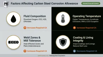
- Fluid composition: dissolved oxygen, CO2, H2S, and chlorides are the primary drivers of carbon steel corrosion rate. Even trace oxygen contamination can meaningfully accelerate attack in an otherwise stable system.
- Operating temperature: higher temperatures generally speed up corrosion kinetics, though CO2 service is an exception, since denser protective scales can slow the rate at certain temperature bands.
- Weld zones and mill tolerance: heat-affected zones corrode differently than parent metal, and mill undertolerance (up to 12.5% below nominal) reduces the wall available for CA.
- Coating and lining integrity: linings, external coatings, and cathodic protection change the corrosion picture and often justify a reduced CA, but the exact reduction should come from project-specific corrosion engineering.
Typical Range of Corrosion Allowance for Carbon Steel
ASME B31.3 doesn't publish a corrosion allowance table for carbon steel. The code requires an allowance; the owner, corrosion engineer, or governing local authority sets the number based on service type and corrosion history.
That said, industry practice tends to cluster around a few recognizable bands.
Nominal and Typical Corrosion Allowance Values
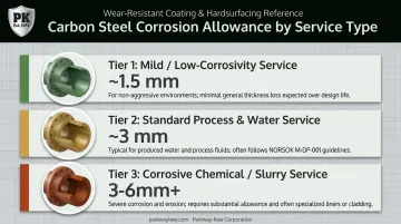
- ~1.5 mm (1/16 in.): mild, low-corrosivity services, often used as a practical floor rather than a calculated figure
- ~3 mm: standard process and water services. This matches the allowance NORSOK M-DP-001 requires for carbon steel piping unless project-specific corrosion data justifies more
- 3-6 mm or more: corrosive chemical or slurry service, where localized wastage is expected on top of general loss
These figures assume a predictable, relatively low corrosion rate, validated by service history, corrosion coupons, or probe data. When that assumption breaks down, so does the CA calculated from it.
Allowable Tolerance and Boundary Limits
Many operators treat 1.5 mm (1/16 in.) as a hard floor for carbon and low-alloy steel piping, regardless of how mild the service looks on paper.
At the other end, CA climbing above roughly 6 mm is usually a red flag. It often signals that carbon steel is the wrong material for the job, and a corrosion-resistant alloy deserves a second look before the design gets locked in.
Safe Operating Margin
Corrosion rate predictions carry real uncertainty, and localized attack rarely shows up in an "average" calculation. Because of this, many engineers build in a margin beyond the bare CR × DL figure, sometimes effectively doubling the calculated value for added confidence.
Running a component close to its CA boundary without that margin has consequences:
- Accelerated inspection frequency to catch localized thinning before it becomes critical
- Derating the component's pressure rating to extend safe service life
- Unplanned shutdown once the wall approaches minimum retirement thickness
Key Properties, Specification, and Measurement of Corrosion Allowance
CA isn't a one-time design entry. It's a specification at the design stage and an ongoing check throughout the component's operating life.
Actual metal loss doesn't always follow the straight line assumed in the original calculation. It can hold steady for years, then accelerate once a protective scale breaks down or process conditions shift. A calculated CA value needs to be checked against real corrosion rate trends, not treated as set-and-forget.
Where CA Gets Documented
- Piping datasheets and line lists, alongside the pressure-design thickness
- Material specifications, distinguishing the "rated" design CA from actual measured wall loss during service
- Inspection records that track remaining thickness against the original design basis
How CA Gets Verified in the Field
Two methods dominate:
- Ultrasonic thickness (UT) gauging: the standard tool for tracking remaining wall thickness at fixed inspection points, with temperature compensation required above roughly 150°F
- Radiographic inspection: often preferred for small-bore pipe (NPS 1 and under) where digital UT readings become unreliable
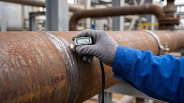
Both feed corrosion rate calculations similar to those used under API 570: long-term rate from initial to current thickness, short-term rate from the two most recent readings, and remaining life from current thickness minus required thickness, divided by rate.
Lab and theoretical corrosion rate data rarely match field-measured rates exactly. Localized pitting, erosion-corrosion at flow disturbances, and MIC all tend to push real-world thinning higher than a lab coupon would suggest, particularly at welds, dead legs, and low-flow zones.
When CA Stops Making Economic Sense
Adding more carbon steel thickness to compensate for a high corrosion rate has a ceiling. Beyond a certain point, the added cost and weight of a thicker wall outweighs the price of upgrading to a corrosion-resistant alloy. Many piping engineers treat CA above roughly 6 mm (0.24 in.) as the signal to run that comparison seriously, rather than defaulting to "just add more thickness."
A third option: apply a wear- and corrosion-resistant coating, such as HVOF-sprayed tungsten carbide, to the existing part instead of upgrading the base metal—an approach Parkway-Kew has supplied since 1952 for oil & gas and industrial wear components.
Implications of Ignoring or Misjudging Corrosion Allowance
Underestimate corrosion allowance, and the consequence is straightforward: wall thickness reaches retirement or minimum structural thickness before the component's intended design life is up. That's not a slow-motion problem. It shows up as unplanned inspection findings, forced derating, or, in worst cases, failure in service.
Common Misjudgments Worth Naming
- Treating a nominal CA figure as an absolute guarantee rather than a modeled estimate based on assumed conditions
- Copying CA values from a past, unrelated project instead of reviewing actual fluid chemistry, temperature, and flow conditions
- Applying stainless-steel-style "near-zero CA" logic to carbon steel, which has no passive protective layer to fall back on
The CSB's investigation into the 2012 Chevron Richmond refinery pipe rupture shows what happens when wall-thickness monitoring falls behind reality. An 8-inch carbon steel pipe installed in 1976 ruptured after severe sulfidation corrosion at temperatures above 600°F, releasing a vapor cloud that sent more than 15,000 residents to seek medical treatment.
Investigators pointed to inspection and mechanical integrity failures, including an unsupported lowering of the minimum alert thickness years earlier.
Restoration as an Alternative to Replacement
Catastrophic failures like Chevron Richmond are rare, but they underscore why a component shouldn't run until its allowance is exhausted. Once corrosion allowance is nearly consumed on a wear-and-corrosion-exposed carbon steel component, full replacement isn't always the only option. This is where hardfacing and thermal spray coating restoration earn their keep.
Parkway-Kew Corporation has spent more than 70 years rebuilding worn carbon steel components across oil and gas, wire drawing, and shipping terminal operations, including:
- Fracking pump plungers, recoated with nickel chrome or fused tungsten carbide after downhole wear and corrosion degrade surface integrity
- Wire drawing blocks and capstans, restored through submerged arc welding, HVOF, plasma spray, or metallizing depending on wire quality and wear profile
- Wire rope pulleys, crane wheels, and festoon wheels, rebuilt for shipping terminal equipment running continuously under heavy load
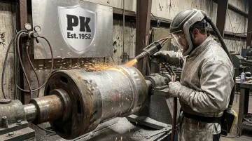
Rather than scrapping a large, worn part once its original wall thickness is spent, sending it out for machining, grinding, and a wear-resistant coating application can restore functional dimensions and extend service life at a fraction of replacement cost. It's a practical middle ground between running a corroded component past its safe limit and buying a new one.
Conclusion
Corrosion allowance is an engineered design margin built into wall thickness calculations from the start. It's derived from corrosion rate, design life, and an applied safety margin, and it shifts as fluid chemistry, temperature, and protective measures change.
Understanding CA's typical range, the factors that shift it, and how it's measured matters for anyone specifying carbon steel pipe, vessels, or heavy equipment. No published range substitutes for engineering judgment, actual service history, and periodic inspection.
When a component's CA does run out, restoration through hardfacing or thermal spray coating can extend its working life well beyond the original design margin, without the cost or lead time of full replacement. Parkway-Kew has offered these restoration techniques since 1952, helping operators extend service life without a full teardown.
Frequently Asked Questions
What is the typical corrosion allowance for carbon steel?
Standard process and water services commonly use 1.5-3 mm of corrosion allowance, while severe corrosive or slurry service can require 6 mm or more. The right figure depends on service history and measured corrosion rate data, not a fixed industry number.
What does ASME code specify for corrosion allowance for carbon steel?
ASME B31.3 does not mandate a fixed CA value for carbon steel. It requires the designer to add an allowance for corrosion and erosion, but the actual figure is set by the owner, corrosion engineer, or governing local authority based on experience.
Is carbon steel susceptible to corrosion?
Yes. Carbon steel lacks the passive protective layer that stainless steel forms, so it corrodes readily in the presence of water, oxygen, acids, and CO2/H2S. That susceptibility is exactly why corrosion allowance gets applied in the first place.
Can corrosion allowance ever be zero for carbon steel?
Rarely. Unlike stainless steel, carbon steel has no inherent corrosion resistance to fall back on. If a near-zero CA is being considered, protective coatings, linings, or a material upgrade should be evaluated instead.
Who decides the corrosion allowance value for a project?
Multiple roles share this decision: process engineering defines how corrosive the service is, corrosion engineers recommend a CA based on that data, and piping engineers apply the figure in thickness calculations.
What happens once the corrosion allowance is fully consumed?
Reaching minimum retirement thickness triggers re-inspection, derating, or replacement. For wear-exposed carbon steel components, coating or hardfacing restoration can sometimes extend service life as an alternative to full replacement.