Introduction
Submerged arc welding has been a workhorse of heavy industry since the 1930s. Yet many engineers and maintenance teams running SAW equipment understand what it does without fully grasping why it behaves the way it does. That gap leads to poor parameter choices, unexpected defects, and process decisions that look reasonable on paper but fail on the floor.
This guide is written for engineers, maintenance managers, and technical procurement teams in wire mills, fabrication shops, oil and gas, and heavy equipment manufacturing. It's an operational-level reference — not a textbook overview — that explains the process, its variables, and where it genuinely excels versus where another process would serve better.
Key Takeaways
- SAW uses a continuously fed electrode and a granular flux blanket that completely covers the arc — eliminating spatter and enabling high deposition rates
- The process excels on thick-section ferrous metals in flat and horizontal positions; it is not general-purpose
- Current, voltage, travel speed, and wire feed speed are the four primary control variables; dial these in before welding — the arc is never visible during the process
- SAW is widely used for hardsurfacing and overlay cladding, not just structural joining — making it a go-to for rebuilding worn industrial components
- Wet flux, incorrect parameter settings, and electrode-flux mismatches are the leading causes of SAW defects
What Is Submerged Arc Welding?
SAW is an arc welding process in which an electric arc forms between a continuously fed consumable electrode and the workpiece, with both the arc and molten weld pool completely shielded by a layer of granular flux. Operators never see the arc during welding.
The process is designed to deliver three things: deep penetration into thick materials, high deposition rates, and consistently clean, uniform welds — with the flux doing the shielding and arc stabilization work that gas or electrode coatings handle in other processes.
How SAW Differs from SMAW and MIG
Two common comparisons are worth clarifying:
- SMAW (stick welding) uses a flux-coated electrode that the operator manually guides with an open, visible arc. SAW feeds electrode continuously and buries the arc entirely under granular flux.
- MIG/GMAW uses shielding gas and an open arc, giving operators full visual access to the weld pool. SAW relies on gravity-deposited granular flux — which is exactly why positional flexibility is far more limited.
One metric that illustrates the productivity gap: according to Miller Electric, single-wire SAW can reach up to 40 lb/h (18.1 kg/h), while multi-torch tandem systems can exceed 100 lb/h (45.4 kg/h). For operations like pressure vessel fabrication, pipe welding, or structural steel production — where thick-section joints run continuously — that output difference directly determines how many shifts a job requires.
How the SAW Process Works
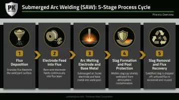
The SAW cycle follows the same sequence on every run:
- Granular flux is deposited ahead of the arc
- The electrode feeds continuously into the flux-covered joint
- Intense arc heat melts both electrode and base metal into a weld pool
- Flux partially melts into a conductive slag that protects and shapes the pool
- Once solidified, slag is removed and unused flux is recovered
Flux plays four active roles during the weld:
- Protects molten metal from atmospheric contamination
- Stabilizes the arc electrically (flux becomes conductive when molten)
- Forms a slag layer that supports and contains the weld pool
- Can contribute alloying elements to modify weld chemistry
On flux recovery: ESAB recommends blending at least 1 part new flux with every 3 parts recycled flux — meaning up to 75% of flux can be reused under that guidance.
Step 1: Workpiece Preparation and Joint Setup
Workpiece cleaning is not optional. Mill scale, rust, and surface contamination within the joint zone must be removed before welding begins. For full-penetration welds, backing bars — steel or copper — control root penetration and prevent burnthrough.
Setup quality directly controls penetration consistency. Because the weld pool is invisible during welding, any joint misalignment or contamination that slips through prep will produce a defect that is only discovered after slag removal.
Step 2: Flux Deposition, Arc Strike, and Active Welding
Flux is laid over the joint via hopper ahead of the electrode. The arc initiates beneath the flux layer — either by touching the electrode to the workpiece or using a starting medium.
From that point, the process is largely self-regulating on DC constant-voltage systems: if the arc shortens, current increases and burns the electrode faster to restore length. The operator or CNC system controls travel speed and monitors parameters digitally, since the pool remains invisible throughout.
Step 3: Cooling, Slag Removal, and Flux Recovery
Once the arc passes, molten slag solidifies over the weld bead. Operators chip or peel it off to reveal the finished weld. Unused surface flux is vacuumed and recycled per the blending ratio above.
Critical for multi-pass welds: full slag removal between passes is required. Any slag left in place becomes an inclusion in the next pass — a common, entirely preventable SAW defect.
Where SAW Is Used: Industries and Applications
SAW's high deposition rate and deep penetration make it most valuable wherever thick-section steel must be welded repeatedly and reliably. Primary industries include:
- Shipbuilding — long hull plate seams
- Pressure vessel and boiler manufacturing — longitudinal and circumferential butt welds
- Pipeline construction — circumferential and longitudinal seams
- Structural steel fabrication — bridges, wind towers
- Heavy equipment manufacturing — frames, booms, and structural weldments
Hardsurfacing and Overlay Cladding
Beyond joining, SAW has a long history in surface restoration — depositing wear-resistant alloy layers onto component surfaces to rebuild worn parts and extend service life. ESAB lists hardfacing filler metals specifically under their Subarc (SAW) product category, confirming this as an established, industrial-scale application.
Parkway-Kew Corporation was an early adopter of this technique, pioneering the use of submerged arc welding for rebuilding and hardsurfacing wire drawing blocks in the 1950s. Founder Eugene Walter Klein proved the concept by welding the first test piece in his garage. He then secured an order to rebuild 100 twenty-six-inch diameter Vaughn wire drawing blocks for CF&I in Roebling, NJ — a contract that established wire drawing hardsurfacing as the company's defining specialty.
Today, Parkway-Kew applies sub-arc welding using two proprietary alloys:
- PK-503 — a super-hard alloy that produces a characteristic heat-checked, cracked surface. Standard choice for most wire drawing applications.
- PK-200 — same hardness as PK-503, but with a different chemistry formulation that deposits virtually crack-free. Used on steel sleeves or steel blocks where surface cracking would be detrimental to wire quality.
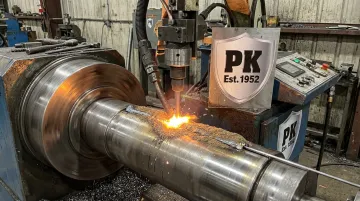
Wire rope pulleys for shipping terminal operations are also rebuilt with the PK-200 alloy — its crack-free deposit makes it well-suited for components where surface integrity directly affects load-bearing performance.
Key Factors That Affect SAW Performance
Welding Parameters
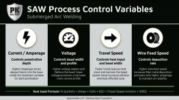
The four primary control variables and their effects:
| Variable | Primary Effect | Practical Note |
|---|---|---|
| Current (Amperage) | Controls penetration depth and deposition rate | Higher current = deeper penetration |
| Voltage | Controls bead width and profile | Higher voltage = wider, flatter bead, less penetration |
| Travel Speed | Controls heat input and bead width | Faster travel = less heat input, narrower bead |
| Wire Feed Speed | Directly controls deposition rate | For a given wire diameter, WFS determines current |
Typical current ranges by wire diameter, per ESAB data: 2.4–2.5 mm wire runs at 300–500 A; 3.2 mm at 350–600 A; 4.0 mm at 400–850 A. Single-wire SAW can range from 200 A with 1.6 mm wire up to 1000 A with 6.0 mm wire.
These four variables must be set together. Adjusting one in isolation changes the heat input, calculated as:
Heat Input = (Voltage × Amperage × 60) / Travel Speed
Shift any single variable without accounting for the others and you risk changes to penetration profile, bead geometry, and mechanical properties simultaneously.
Electrode Selection
Wire diameter, composition, and configuration must match the base metal and joint design:
- Diameter range: Typically 1.6–5.0 mm for single-wire SAW
- Compositions: Carbon steel, stainless, low-alloy, or cored wire
- Configurations: Single wire, twin wire (20–30% higher deposition over single-wire DC), or strip electrode for cladding
An incompatible electrode changes both the mechanical properties of the finished weld and its geometry. Substituting electrode types without an updated, reviewed WPS risks both mechanical failure and dimensional defects.
Flux Type and Condition
The three main flux types each have distinct manufacturing methods and use cases:
- Fused flux — ingredients melted together, then crushed and granulated. Chemically homogeneous, stable.
- Bonded/agglomerated flux — components rolled with silicates, dried, and baked at roughly 600–850°C. Allows alloying and deoxidizing additions not easily retained in fused flux.
- Mechanically mixed flux — blends of fused or agglomerated fluxes with additional components. Verify supplier classification and WPS compatibility before use.
Moisture content is the critical variable. Wet flux causes porosity and hydrogen-induced cracking. ESAB specifies rebaking at 350°C ± 25°C for a minimum of 4 hours, with flux depth not exceeding 50 mm on shallow plates. Flux storage and pre-use drying are process controls, not optional housekeeping steps.
Positional Constraints and Power Source
SAW is restricted to flat (1G, 1F) and horizontal-fillet (2F) positions. Molten flux and the weld pool are fluid and gravity-dependent — attempting vertical or overhead welding without specialized support causes flux loss, pool instability, and weld failure.
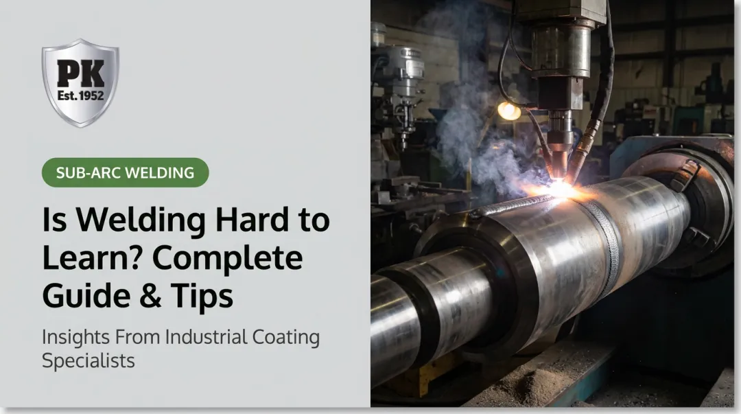
In practice, workpiece positioners and column-and-boom setups are standard equipment for SAW on cylindrical or large structural components. On rotational parts such as wire drawing blocks, the workpiece rotates under a stationary or traversing weld head — keeping the joint in the flat position throughout and allowing consistent bead deposition across the full surface.
Power source polarity choices:
| Polarity | Penetration | Deposition Rate | Best Use |
|---|---|---|---|
| DCEP (electrode positive) | Maximum | Moderate | Applications requiring deep penetration and arc stability |
| DCEN (electrode negative) | Lower | Highest | High-deposition passes where penetration can be sacrificed |
| AC | Balanced | Balanced | Multi-wire setups; reduces arc blow |
Common Misconceptions and When SAW Isn't the Right Choice
Misconception: "No visible arc means the process is safe to run unsupervised"
The hidden arc actually increases the risk of undetected errors. Because the operator cannot see the weld pool, any incorrect parameter, flux gap, or joint misalignment produces a defect that is only discovered after slag removal. Continuous parameter monitoring in SAW is more critical than in open-arc processes.
Misconception: "SAW works on any metal and any thickness"
The real constraints:
- Compatible metals: Carbon steels, low-alloy steels, stainless steels, and select nickel-based alloys. Routine SAW on aluminum or titanium is not supported by accepted process guidance.
- Minimum thickness: SAW is suited to material from approximately 3/16 in (4.76 mm) upward, with the practical sweet spot at 1/2–5 inches. Below that lower limit, the heat input causes excessive distortion and burn-through. MIG, FCAW, or TIG are better suited for thin-section work.
When SAW Is the Wrong Choice
Material and thickness limits are only part of the picture. There are also situational mismatches where SAW simply isn't practical — regardless of what's in the equipment bay. Choose an alternative process when:
- Vertical or overhead welds are required — standard SAW is limited to flat and horizontal positions
- The job is field- or site-based — SAW requires infrastructure (flux hopper, recovery system, positioner) that isn't portable
- Welds are short and intermittent — setup overhead makes SAW inefficient for anything but continuous or rotational seams
- The base metal is non-ferrous — use GMAW or GTAW instead
Process selection should always start with joint requirements. Defaulting to SAW because the equipment is on hand — without confirming position, material, and seam length — is one of the more avoidable sources of rework in production welding.
Frequently Asked Questions
How does SAW compare to SMAW and TIG?
SAW's arc is hidden under flux — unlike SMAW and TIG, where the arc is visible and accessible in all positions. Deposition rates are far higher, but SAW is limited to flat and horizontal positions. TIG is preferred for precision work on thin sections; SMAW offers the most positional versatility.
What materials can be welded using submerged arc welding?
Carbon steels, low-alloy steels, stainless steels, and select nickel-based alloys are all routinely welded with SAW. The process is not practical for aluminum, titanium, or most non-ferrous metals.
What welding parameters most affect SAW weld quality?
The four primary variables are current (penetration), voltage (bead width), travel speed (heat input), and wire feed speed (deposition rate). They must be balanced together; adjusting one without accounting for the others shifts the overall heat input and weld profile.
Can SAW be used for hardsurfacing and overlay cladding?
Yes. SAW is widely used for wear-resistant overlay and component rebuilding, depositing hard alloy layers on worn surfaces. Parkway-Kew Corporation has applied sub-arc welding to rebuild wire drawing blocks and other industrial components since the 1950s.
What causes weld defects in submerged arc welding?
The most common causes are wet or contaminated flux (porosity, hydrogen cracking), incorrect parameter settings, poor joint preparation, and electrode-flux incompatibility. Since the weld pool is invisible, defects won't surface until after welding unless parameters are actively monitored.
What is the minimum material thickness for submerged arc welding?
SAW can be used down to approximately 3/16 in (4.76 mm) with controlled heat input, though it performs best on material 1/2 inch and thicker. Below that lower limit, heat input causes distortion and burn-through — GMAW or FCAW are more appropriate alternatives.