
This guide is written for machine shop buyers, engineers, and maintenance teams working in heavy industrial, oil & gas, and manufacturing environments — the kind of operations where a shaft out of round by a few thousandths can shut down a production line.
Turning gets used as a catch-all term in manufacturing, but it covers a wide range of operations, methods, and failure points. This guide breaks down how turning works, the operations and taper methods under that umbrella, the variables controlling your results, and when turning isn't the right call at all.
Key Takeaways
- A single-point tool cuts a rotating workpiece into cylindrical, tapered, or contoured shapes.
- CNC lathes deliver tighter repeatability than manual lathes on complex geometries.
- Cutting speed, feed rate, and depth of cut control finish, tool life, and cycle time.
- Straight turning, facing, grooving, parting, threading, and boring cover most lathe work.
- Non-rotational or highly asymmetric parts are usually better suited to milling.
What Is the Turning Process?
Turning is a machining operation in which a single-point cutting tool removes material from a workpiece rotating on a lathe, producing a target diameter, length, or profile.
The ASM Handbook defines turning as generating external surfaces of revolution through the action of a cutting tool on a rotating workpiece, a definition built around motion, not just the equipment involved.
The goal is straightforward: dimensional accuracy, concentricity, and a controlled surface finish on rotational parts. Shafts, rollers, pump plungers, and drawing blocks all depend on turning to hit those targets consistently, pass after pass.
Turning vs. Boring vs. Facing
These terms get used interchangeably on shop floors, but they describe different tool motions on different surfaces:
- Turning removes material from external, rotating surfaces to set outside diameter.
- Boring enlarges and refines existing internal holes, serving as the internal equivalent of turning.
- Facing cuts the end of the workpiece to establish length and a flat face.
Why does turning dominate rotational-part manufacturing? It delivers tight tolerances, repeatable results across long production runs, and smooth finishes without extra secondary processing, on parts ranging from a two-inch shaft to a multi-ton wire drawing block.
Skip a step, though, and problems show up fast:
- Out-of-round parts from unstable workholding or excess tool overhang
- Poor surface finish from mismatched speed and feed
- Premature tool wear from the wrong tool material or geometry
- Dimensional drift across a run as inserts wear
None of this is regulatory. No code mandates turning for a given part. It gets chosen because, for rotational geometry, it balances speed, accuracy, and cost better than any alternative process.
How the Turning Process Works (Conceptual Flow)
At a basic level, turning secures a workpiece, rotates it at a controlled speed, and engages it with a cutting tool that shears away material in the form of chips. Everything else is refinement of that core idea.
Inputs feeding into the process:
- Raw stock (bar, casting, or forging)
- A lathe, manual or CNC
- A single-point cutting tool
- Workholding (chucks, collets, or centers with a tailstock)
As the tool advances along or into the rotating workpiece, it shears away layers of material until the part reaches its target diameter, taper, or feature.
Cutting speed (rpm), feed rate, and depth of cut depend on material hardness, tool type, and the finish required. Get those settings wrong, and the mistake shows up in surface finish and tool life long before it shows up on the tolerance sheet.
The result: a dimensionally accurate, concentric part with a specified surface finish, ready for a secondary operation or final assembly.
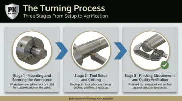
Step 1: Mounting and Securing the Workpiece
A chuck, collet, or centers-and-tailstock setup holds the workpiece firmly in place. It needs to rotate true to the spindle axis without vibration; any runout here carries through every subsequent cut.
Step 2: Tool Setup and Cutting
The operator, or the CNC program, positions the single-point tool at the correct rake, relief, and cutting-edge angle, then advances it into the rotating workpiece along a programmed or manual path. Roughing passes remove bulk material fast; finishing passes take light cuts to hit final dimensions.
Step 3: Finishing, Measurement, and Quality Verification
After finishing passes refine the surface, the operator checks the part with micrometers, calipers, or a CMM to confirm it holds tolerance before release. On large-diameter components (a 40-inch wire drawing block, for instance), this step matters even more, since small deviations translate into significant material removed or added back in a rework pass.
Types of Turning Operations and Where They're Applied
Turning covers more ground than simple diameter reduction. Here's how the core operations break down.
Straight (cylindrical) turning reduces a workpiece to a uniform diameter along its length, typically as a roughing pass before finishing cuts refine the surface.
Taper turning produces a gradually changing diameter, used on spindles, shafts, and fittings that need a conical end.
Four Methods of Taper Turning
The method depends on the taper's length and angle:
- Compound slide method: Swivels the compound rest to the required taper angle, feeding the tool manually. Best for short, steep tapers.
- Tailstock set-over method: Offsets the tailstock center from the spindle centerline, producing a long, gradual taper as the workpiece turns between centers.
- Taper turning attachment method uses a guide bar and shoe to control cross-slide motion independently of the tailstock, preserving alignment for repeat work.
- Form tool method: Uses a cutting edge ground to the exact taper profile, plunged into the rotating stock for short tapers in a single pass.
Beyond straight and taper turning, most lathe work falls into a handful of other operations:
- Facing squares off end faces and sets part length.
- Grooving cuts precise recesses for retaining rings, O-rings, or relief cuts.
- Parting separates a finished component from the remaining bar stock.
- Thread turning cuts helical grooves for fasteners using a profiled tool synced to spindle rotation.
- Knurling presses a grip pattern into the surface rather than cutting it (a forming operation, not a cutting one).
- Boring and drilling often round out the same setup: drilling starts a bore, and boring enlarges and refines it for size, roundness, and concentricity.
Large-Diameter and Heavy Industrial Turning
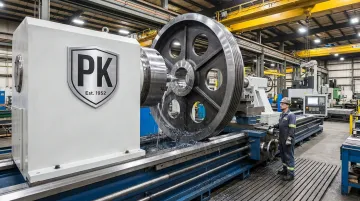
Some applications need lathes that standard shops simply don't carry: large rollers, drums, capstans, or wire drawing blocks that run well beyond typical shop capacity.
Parkway-Kew maintains in-house CNC and manual turning up to 72 inches in diameter, plus large-diameter grinding capacity up to 65 inches in diameter and 12 feet in length. That capacity supports restoration work most shops can't touch: rebuilding wire drawing blocks and capstans, crane wheels, wire rope pulleys, and trolley festoon wheels for wire mills and shipping terminal operations across North America.
Turning doesn't always pair with a coating step. Solid tungsten carbide parts get machined and shipped without any additional coating.
Key Factors That Affect Turning Performance and Precision
Four variables determine whether a turning job hits tolerance on the first pass or ends up back on the machine.
- Material properties. Hardness and machinability dictate achievable cutting speeds and tool material choice.
- Cutting parameters. Speed, feed rate, and depth of cut each shape tool life and surface finish.
- Tool geometry and material. Carbide, HSS, nose radius, and rake angle all affect cutting force and heat generation.
- Machine and workholding rigidity. Chuck and collet accuracy, plus bed capacity, become critical as parts scale up.
Here's why each factor matters in practice:
Hardened steel in the 45-65 HRC range needs an entirely different approach than free-machining aluminum, from tool coating to spindle speed.
Sandvik Coromant identifies cutting speed as having the greatest effect on tool life among these three parameters. Push it too high and flank wear accelerates; push it too low and built-up edge ruins the finish.
Carbide holds up under heat and abrasion far better than high-speed steel, though HSS stays tougher and cheaper for lower-volume or custom-profile work.
Sandvik also flags tool overhang beyond roughly four times the bar diameter as a stability risk. That risk only grows on large-diameter, heavy industrial components, where rigidity has to be engineered into the workholding itself.
Common Issues, Misconceptions, and When Turning May Not Be the Right Choice
"Turning only makes simple cylinders." Not true. The same process produces tapers, contoured profiles, threads, and grooved features : straight OD reduction is just the starting point.
Turning, boring, and facing get used interchangeably, but they're distinct tool motions on distinct surfaces. Mixing them up in a spec or work order leads to running the wrong setup.
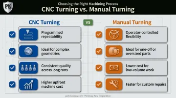
"CNC removes the need for skilled setup." Also not true. Programming, tool offsets, and fixturing still require an experienced operator to hold tight tolerances — software doesn't compensate for a poorly planned setup. Manual turning still earns its keep, too: Modern Machine Shop documented a shop retaining manual lathes for a 22-foot-long, 8-inch-diameter shaft where buying a comparably sized CNC machine wasn't economically justified. Parkway-Kew's own shop relies on manual lathes for the same reason, turning oil-and-gas plungers and wire-mill blocks up to 72 inches in diameter where a CNC retrofit wouldn't pay for itself.
Turning isn't the right call for every part, though:
- Non-rotational or highly asymmetric geometries: milling handles flats, pockets, and off-axis features far more efficiently.
- Ultra-high-volume simple parts: multi-spindle screw machines outproduce single-spindle lathes on long runs of small, repetitive components.
- Parts dominated by milled features: if a part is mostly flat faces and off-axis holes, running it on a lathe by default costs more time and money than it should.
Shops that default to turning simply because that's the equipment on hand, rather than because the geometry calls for it, pay for it: the part runs slower and costs more than it should.
Frequently Asked Questions
What are the 4 methods of taper turning?
The compound slide method, tailstock set-over method, taper turning attachment method, and form tool method. Each suits a different taper length and angle, from short steep tapers to long gradual ones.
What is the basic turning procedure?
Mount the workpiece securely, set up and position the cutting tool, then run roughing and finishing passes as the part rotates. Measure and verify dimensions before releasing the part.
How do you calculate machining time for turning?
Divide the length of cut by the product of feed rate and spindle speed (rpm). Multiple passes multiply this base time, so roughing and finishing passes get calculated separately.
What is the difference between turning and milling?
Turning rotates the workpiece against a stationary or moving single-point tool to create cylindrical shapes. Milling rotates the cutting tool against a stationary workpiece to produce flat or complex 3D features.
What materials can be turned on a lathe?
Most metals, including steel, aluminum, brass, titanium, and stainless steel, can be turned, along with plastics and some woods. Material hardness drives tool choice and cutting parameters more than anything else.
What's the difference between CNC turning and manual turning?
CNC turning uses programmed, computer-controlled movements for high repeatability on complex geometries. Manual turning relies on operator control, better suited to one-off jobs, repairs, or oversized parts.