Introduction
Specifying the wrong maximum temperature for an industrial ceramic coating doesn't just shorten coating life — it causes premature spalling, unplanned component failures, and costly downtime in environments where stopping the line is never a small problem.
Maximum temperature is consistently misread in industrial practice. Engineers pull a number from a datasheet, treat it as a continuous operating target, and wonder why the coating fails ahead of schedule. In practice, maximum temperature is a system-level property — not a single fixed number — and it behaves very differently under continuous exposure versus intermittent peak conditions.
This guide breaks down what you need to know to specify correctly:
- What maximum temperature actually means for industrial ceramic coatings
- How temperature limits vary across material types and application methods
- Which thermal properties govern performance under sustained heat
- How to specify and validate maximum temperature for your application
Key Takeaways
- Maximum temperature is a system-level rating — ceramic layer, bond coat, and substrate must all be evaluated together.
- Continuous and peak/intermittent temperature limits are different values; treating the peak limit as a continuous target accelerates failure.
- YSZ grade matters: 8 wt.% YSZ is rated to 2,280°F, while 20 wt.% YSZ reaches 2,730°F.
- Chromia (Cr₂O₃) is a wear/corrosion ceramic rated to ~1,000°F — not a thermal barrier substitute.
- Running near the rated maximum — even without exceeding it — drains coating life far faster than maintaining a proper service margin.
What Maximum Temperature Really Means in Industrial Ceramic Coatings
The System, Not Just the Ceramic
Maximum temperature is the upper thermal threshold at which a ceramic coating maintains structural integrity, adhesion, and its protective function. The ceramic material's melting point is substantially higher than its service temperature — that gap is where misspecification happens.
Oerlikon Metco's alumina powder datasheet makes this concrete — Al₂O₃ carries a melting point of 2,054°C, while its listed service temperature ceiling is 1,650°C (3,000°F). Using oxide melting points as coating temperature ratings leads directly to under-specification.
Maximum temperature is a system-level constraint, not a material-only property. NASA's thermal barrier coating research describes TBC performance as a function of the interaction between the ceramic topcoat, the metallic bond coat, and the substrate — thermophysical and thermomechanical properties all contribute.
A ceramic that is thermally capable in isolation can still fail if the bond coat degrades or if the substrate expands faster than the coating can tolerate.
Continuous vs. Peak Exposure
Understanding system-level limits leads directly to a second specification trap: confusing continuous and peak ratings. The two numbers are not interchangeable:
- Continuous service temperature — the maximum the coating can sustain indefinitely without degradation
- Peak/intermittent temperature — a higher ceiling the coating can briefly tolerate before thermal cycling damage accumulates
These are not the same number. A coating rated to 2,280°F in intermittent service may have a meaningfully lower continuous limit. Applying the peak figure as a design target for continuous operation is one of the most common specification errors in industrial thermal spray work.
Real-World Factors That Shift the Limit
Field conditions routinely push coatings past their lab-rated performance. The factors that matter most:
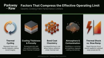
- Thermal cycling — repeated heat/cool cycles induce mechanical stress at the ceramic-substrate interface through differential thermal expansion, often more damaging than steady-state high temperature
- Coating thickness and porosity — thicker coatings sustain larger thermal gradients; conventional APS TBC porosity ranges from 5–15%, which is a feature that accommodates strain, not a defect
- Bond coat chemistry — Oerlikon lists NiCrAlY/NiCoCrAlY bond coat materials with a maximum service temperature of 1,050°C (1,920°F), meaning the bond coat can become the limiting component before the ceramic topcoat approaches its ceiling
- Atmosphere and contamination — oxidizing vs. reducing environments, molten metal splash, and chemical contaminants all compress the effective operating limit
- Thermal shock vs. slow ramp — rapid thermal shock is far more damaging than gradual heating to the same peak temperature
Temperature Ranges by Industrial Ceramic Coating Type
Nominal Operating Ranges by Material
Not all ceramic coatings operate in the same thermal neighborhood. The table below summarizes verified service temperature limits from manufacturer data:
| Coating Material | Service Temperature Ceiling | Primary Strength | Common Applications |
|---|---|---|---|
| Alumina (Al₂O₃) | ≤ 1,650°C / 3,000°F | Wear resistance, electrical insulation | Industrial rolls, wire drawing |
| 8 wt.% YSZ | ≤ 1,250°C / 2,280°F | Thermal barrier | Turbine components, kiln furniture |
| 20 wt.% YSZ | ≤ 1,500°C / 2,730°F | Enhanced thermal barrier | Extreme heat environments |
| Chromia (Cr₂O₃-TiO₂) | ≤ 540°C / 1,000°F | Wear and corrosion resistance | Wire drawing, chemical environments |
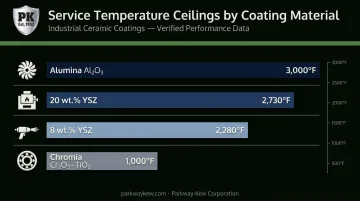
Oerlikon's Cr₂O₃-TiO₂ datasheet lists chromia's service temperature ceiling at just 540°C (1,000°F). It is a wear and corrosion coating, not a thermal barrier coating alternative.
This distinction matters for Parkway-Kew's PK-1500 chrome oxide, which is applied for wear resistance on wire drawing blocks — not for thermal insulation.
The 2,280°F ceiling applies only to 8 wt.% YSZ formulations; the higher 2,730°F figure applies to 20 wt.% YSZ. Citing generic "YSZ" ratings without specifying the grade creates real specification risk.
Plasma Spray vs. HVOF: Process Effects on Thermal Limits
The application method changes both the coating's microstructure and its thermal behavior:
Plasma spray (APS):
- Produces a lamellar, porous structure (5–15% porosity in conventional TBCs)
- Porosity reduces thermal conductivity — NASA data shows plasma-sprayed YSZ achieves ~1 W/m·K versus the intrinsic ~2.5 W/m·K, because micropores and microcracks interrupt heat transfer
- Better suited to very high thermal environments where controlled porosity provides the strain tolerance needed to survive cycling
- Can deposit oxide ceramics at temperatures HVOF cannot reach
HVOF:
- Produces a denser, harder coating with minimal porosity
- Better mechanical bond strength and wear resistance
- Oerlikon's WC-20CrC-7Ni HVOF material carries a maximum service temperature of 700°C (1,290°F) — suited to combined wear and moderate heat, not high-temperature insulation
- Chromium carbide-NiCr cermets extend this to 540–870°C (1,000–1,600°F)
HVOF carbide coatings like those Parkway-Kew applies to wire drawing blocks and fracking plungers deliver outstanding wear resistance in moderate heat environments. When the application shifts to extreme thermal insulation — turbine hot sections, kiln furniture — plasma-sprayed YSZ takes over, because its controlled porosity is an advantage, not a limitation.
Properties That Govern Performance at High Temperature
Thermal Conductivity
Low thermal conductivity is what makes YSZ valuable as a thermal barrier: it sustains a large temperature drop across a thin coating layer, protecting the substrate metal underneath. Plasma-sprayed YSZ achieves ~1 W/m·K in service, roughly half the intrinsic value, because pores and microcracks interrupt conduction.
Alumina conducts heat more readily than YSZ, making it better suited to wear protection and electrical insulation than to thermal insulation.
CTE Compatibility and Bond Coats
Coefficient of thermal expansion (CTE) mismatch between the ceramic topcoat and metal substrate is the primary driver of delamination under thermal cycling. Peer-reviewed data puts YSZ CTE at 11 × 10⁻⁶ K⁻¹, alumina TGO at 9.3 × 10⁻⁶ K⁻¹, and MCrAlY bond coats at 17.5 × 10⁻⁶ K⁻¹.
These numbers explain why the bond coat acts as a mechanical bridge between the ceramic and the metal substrate. Bond coat selection directly determines the practical upper temperature limit of the full system.
Phase Stability
Ceramic materials can undergo destructive phase transformations at specific temperatures. Pure zirconia transitions from tetragonal to monoclinic below 1,170°C — a transformation that involves a volume change that cracks the coating from within. Yttria stabilization suppresses this transformation, which is why YSZ is specified rather than pure ZrO₂ for thermal barrier applications. The grade-specific service limits (2,280°F vs. 2,730°F) reflect the yttria content's effect on phase stability at extreme temperatures.
Thermally Grown Oxide (TGO) Formation
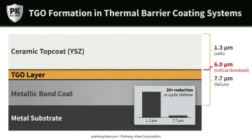
At elevated temperatures, oxidation of the metallic bond coat layer creates a thermally grown oxide (TGO) layer at the ceramic-metal interface. This is the dominant long-term failure mechanism in thermal barrier systems. Research published in the Journal of the American Ceramic Society quantifies the effect starkly: increasing initial TGO thickness from just 1.3 µm to 7.7 µm reduced APS TBC thermal cyclic lifetime by approximately 20 times under 1,150°C peak surface temperature cycling.
Key TGO failure thresholds to understand:
- ~6.0 µm: Critical thickness identified as the failure onset threshold for APS TBC systems
- Continuous growth: TGO accumulates even when the ceramic topcoat temperature rating has not been exceeded
Coating life is consumed by bond coat oxidation regardless of surface thermal performance — a failure mode that operates independently of whether the ceramic itself has been overloaded.
How Maximum Temperature Is Specified and Validated
Reading Datasheets Correctly
Industrial ceramic coating datasheets can list three distinct temperature values that are often confused:
- Gas/flame temperature — the temperature of the heat source, which is always higher than the coating surface
- Coating surface temperature — what the outer ceramic layer actually experiences
- Substrate temperature — what the metal component underneath sees
These values can differ by hundreds of degrees. Specifying against gas temperature when the rating applies to substrate temperature leads to severe under-specification. For complex applications, an experienced thermal spray provider can align material selection to actual operating conditions rather than datasheet assumptions. Parkway-Kew Corporation has applied industrial coatings across oil and gas, wire drawing, and heavy industry for 74 years.
Field Measurement Methods
Surface temperature measurement in service is harder than it appears:
| Method | Practical Notes |
|---|---|
| Laser (IR) pyrometer | Useful for moving components; emissivity errors common on ceramic surfaces — low-emissivity materials under-report temperature |
| Embedded thermocouple | Measures substrate temperature near the coating interface; placement critical |
| Thermal paint indicators | Rolls-Royce data shows accuracy of ±20°C below 500°C, ±4% above 500°C; usable in areas without line-of-sight |
ASTM E2847-21 covers calibration and accuracy verification for wideband IR thermometers below 1,000°C. For high-temperature industrial applications, field measurements should be taken at multiple points and across multiple stages of the thermal cycle — a single spot measurement at one moment rarely captures the true peak.
Beyond the Thermal Limit: Failure Modes and Misinterpretations
The Failure Sequence
When a coating operates at or above its maximum temperature, failure progresses in a specific sequence. Visible spalling is the last event, not the first:
- TGO accelerates — oxidation of the bond coat intensifies, growing the TGO layer toward the critical ~6 µm threshold
- Sintering begins — high-temperature sintering densifies the porous ceramic microstructure, increasing elastic modulus (NASA data shows APS TBC elastic modulus rising from 70 GPa to 125 GPa over 20 hours of extreme exposure) and eliminating the strain tolerance that prevented cracking
- Microcracking develops — detectable under inspection before spalling; changes in surface hardness or finish indicate phase transformation has begun
- Delamination progresses — interfacial cracking at the bond coat driven by TGO growth stress
- Spalling occurs — visible failure, often weeks or months after internal degradation began
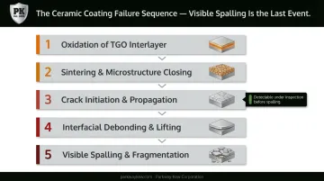
The lag between internal degradation onset and visible surface failure means routine inspection often catches it too late.
The Most Common Misinterpretation
In industrial settings, the published maximum temperature is routinely treated as the continuous operating target rather than an absolute upper ceiling. This is a critical specification error.
Sustained operation at or near the rated maximum consumes coating life dramatically faster — up to 20× faster based on TGO thickness data than operation within a proper service margin — even when no single thermal event technically exceeds the limit. That nonlinearity is the core risk: small, persistent overloads compound catastrophically, not gradually.
Specification errors don't only come from misreading temperature limits — they also come from sourcing the wrong product category entirely. Industrial high-temperature thermal spray ceramic coatings are categorically different from automotive SiO₂-based ceramic coatings (paint sealants), which are rated for a few hundred degrees at most. Conflating these two categories when sourcing for industrial applications results in severe under-specification.
Frequently Asked Questions
What material can withstand 3,000°F?
Plasma-sprayed alumina (Al₂O₃) is rated to a service temperature of ≤3,000°F per Oerlikon Metco data. Advanced YSZ formulations at higher yttria content approach but generally fall below this threshold — 20 wt.% YSZ is rated to 2,730°F. Reaching and sustaining 3,000°F in service requires full-system design, including compatible bond coats and substrate selection.
How cold is too cold to apply ceramic coating?
Industrial thermal spray processes (plasma spray, HVOF) generate extreme heat at the spray gun and are largely independent of ambient air temperature. The critical requirement is substrate condition: most thermal spray specifications require the substrate to be dry and at least 5°F above the dew point to prevent moisture-related adhesion failure at the coating interface.
Does a 5-year ceramic coating actually last 5 years in industrial environments?
Service life depends on operating margin, thermal cycling severity, and whether chemical or mechanical wear is also present. A correctly specified coating can meet or exceed its rated life; one operating near its temperature limit or in an under-specified environment will degrade prematurely regardless of any nominal warranty.
What is the maximum temperature for plasma spray ceramic coatings?
Plasma-sprayed alumina is listed at ≤3,000°F service temperature. Plasma-sprayed 8 wt.% YSZ is rated to ≤2,280°F, while 20 wt.% YSZ reaches ≤2,730°F. Chromia-based plasma spray coatings, such as Parkway-Kew's PK-1500 chrome oxide used on wire drawing blocks, are rated to ≤1,000°F — appropriate for their wear-resistance role, not thermal barrier service.
What is the difference between HVOF and plasma spray for high-temperature ceramic applications?
HVOF produces a denser coating with superior wear resistance at moderate temperatures (generally up to ~1,290°F for WC-based cermets), making it the right choice for components like wire drawing blocks and fracking plungers where abrasive wear is the primary threat. Plasma spray achieves higher temperature capability and produces the controlled porosity required for thermal barrier performance. The correct process depends on whether the primary threat is wear, heat insulation, or both.
What happens to ceramic coating if it exceeds its temperature limit?
Exceeding the maximum temperature sinters the porous microstructure and accelerates TGO growth at the bond coat interface, eliminating the strain tolerance that resists thermal cycling damage. The result is progressive delamination and eventual spalling. Internal degradation begins well before any surface change is visible: inspection may show a sound coating while significant subsurface damage has already accumulated.