For engineers, procurement managers, and operations teams in wire drawing, oil and gas, heavy equipment, and industrial manufacturing, understanding which process fits a given component isn't academic — it's operational. A mismatched process or an imprecise substrate can compromise coating adhesion, accelerate wear, and cause the kind of downtime that costs far more than the part itself.
According to Protolabs, standard CNC machining holds ±0.005 in. (0.13 mm), while precision-grade work reaches ±0.002 in. (0.051 mm) — and reamed holes can achieve ±0.0005 in. (0.0127 mm). Those distinctions matter enormously when a wire drawing block, fracking plunger, or crane sheave has to perform reliably in high-wear environments.
This article breaks down how each process works, when to use each one, and what factors actually determine whether a machined part meets spec.
Key Takeaways
- CNC turning rotates the workpiece; the cutting tool is stationary — ideal for shafts, cylinders, and axially symmetric components
- CNC milling rotates the cutting tool while the workpiece stays fixed — suited for flat surfaces, pockets, profiles, and complex 3D geometry
- Both processes run G-code programs from CAD/CAM software, producing consistent, repeatable dimensions across entire production runs
- Part geometry determines which process to use — not operator preference or shop convention
- Most industrial components require both turning and milling at different stages, including pre- and post-coating work to hold final tolerances
What Are CNC Turning and Milling?
CNC Turning
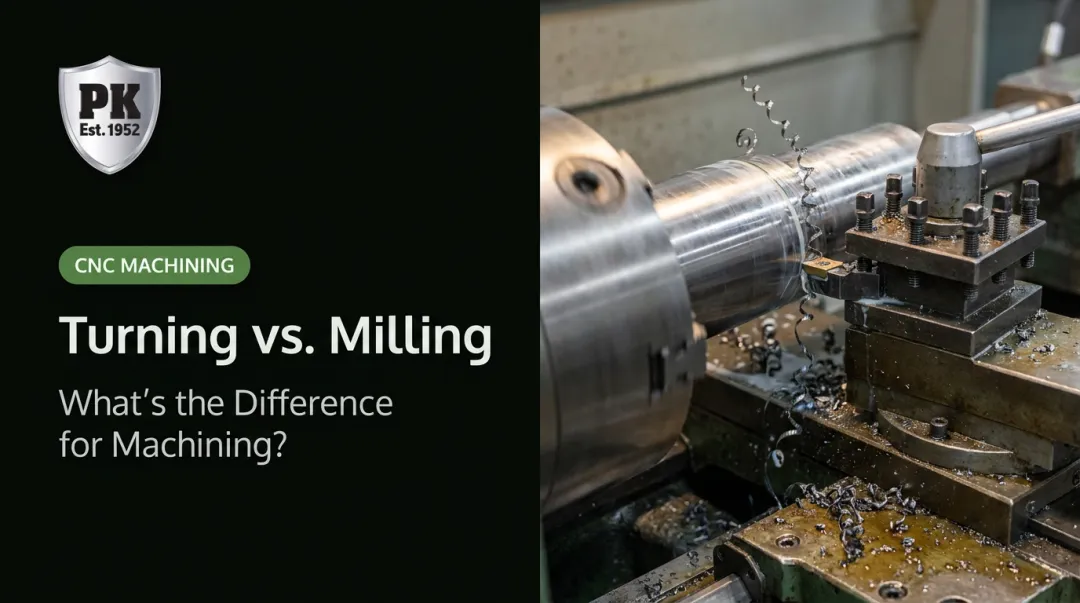
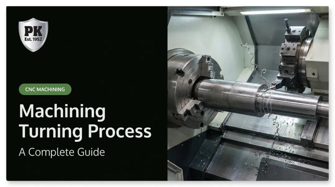
In CNC turning, the workpiece is held in a chuck and rotated at high speed while a stationary cutting tool moves along two axes to remove material. This produces cylindrical, conical, and axially symmetric shapes — shafts, bushings, rolls, capstans, and bores. If the part's geometry is rotationally symmetric, turning is almost always the right starting point.
Sandvik Coromant defines turning as a process where the tool is stationary while the workpiece rotates. Common operations include:
- External: longitudinal turning, profile turning, face turning
- Internal: boring, threading
CNC Milling
In CNC milling, the cutting tool rotates and traverses multiple axes while the workpiece remains fixed. This enables the production of flat surfaces, pockets, slots, contours, and three-dimensional profiles — parts that are prismatic rather than rotationally symmetric.
Multi-axis milling extends this further. For complex part geometries, simultaneous 5-axis machining — as DMG MORI notes — can produce intricate contours in a single operation without reclamping. That matters: every additional setup introduces potential for feature-to-feature error that compounds across tight tolerances.
What Both Processes Share
- Both are subtractive manufacturing methods driven by G-code derived from CAD/CAM software
- Both achieve tolerances of ±0.002 in. (0.051 mm) at precision grade, with tighter feature-specific tolerances available
- Both serve prototyping and production volumes across industries
- Both are foundational to coating workflows: substrate geometry must be correct before any thermal spray or HVOF coating is applied
How CNC Turning and Milling Work
Both processes follow the same high-level workflow: a CAD model is converted into machining instructions via CAM software, loaded into the CNC controller, and executed as the machine cuts raw stock to shape. That automation removes reliance on manual operator skill for repeatability — once programmed, the machine replicates the same cut across every part in the run.
CNC Turning: Step-by-Step
Step 1: Workpiece Setup
Raw stock is secured in the chuck or between centers. Proper centering and clamping directly affect roundness and concentricity — any runout in the setup transfers to the finished part. For components like wire drawing blocks or fracking plungers, concentricity at this stage determines performance in service.
Step 2: Cutting Operations
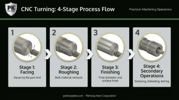
As the workpiece rotates, the programmed tool traverses radially and axially. A typical sequence includes:
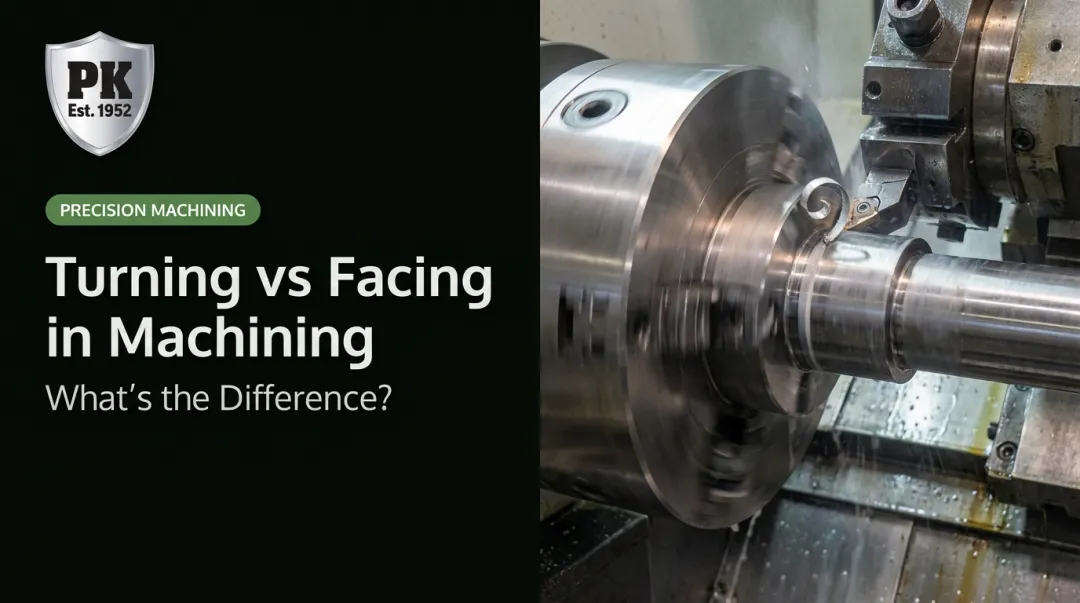
- Facing — squaring the end of the part
- Roughing — bulk material removal to approximate shape
- Finishing — cutting to final diameter and surface finish
- Secondary operations — grooving, threading, boring, performed in sequence or via live tooling on equipped machines
Surface finish is driven by feed rate, nose radius, and insert geometry. Sandvik data shows a 0.8 mm nose radius at 0.20 mm/rev produces Ra 1.25 µm, while a wiper insert at the same feed achieves Ra 0.35 µm.
For hardened steels above 55 HRC, PCBN tooling is required, with cutting speeds in the 80–300 m/min range.
Step 3: Inspection and Finishing
Dimensional verification against tolerances using gauges and CMM equipment, followed by deburring, grinding where required, or preparation for coating application.
Where turning shapes parts through rotation, milling achieves precision through a moving cutter — making it the preferred method for complex geometries and prismatic components.
CNC Milling: Step-by-Step
Step 1: Fixturing the Workpiece
The raw material is clamped to the machine table or held in a vise. Rigidity is non-negotiable — any movement during cutting translates directly into dimensional error. For large industrial components, this often means custom fixturing.
Step 2: Cutting Operations
The rotating cutter traverses programmed paths in X, Y, and Z — and additional rotational axes in 4- or 5-axis configurations. Automatic tool changers allow multiple tool types to run in a single setup. Operations include:
- Face milling and slot milling
- Profiling and contouring
- Drilling and boring
- Pocket milling for keyways, bolt patterns, and recesses
Step 3: Inspection and Surface Finishing
Inspection of critical dimensions and surface finish (Ra values), followed by deburring and any secondary coating or treatment. For components that will receive HVOF tungsten carbide coatings (which reach 1,200–1,500 HV), diamond grinding is the standard finishing route after coating, not turning or milling.
CNC Turning vs. Milling: Choosing the Right Process
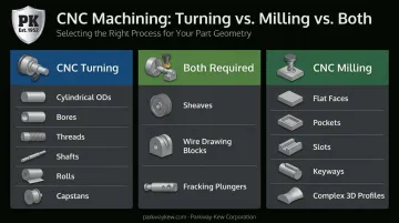
The primary decision rule is straightforward: geometry determines process.
| Part Feature | Correct Process |
|---|---|
| Cylindrical OD, bores, threads | CNC Turning |
| Flat faces, pockets, slots, keyways | CNC Milling |
| Complex 3D profiles | CNC Milling (4- or 5-axis) |
| Mixed cylindrical + milled features | Turn-Mill or Sequential Operations |
When to Use Turning
Choose turning for shafts, rolls, cylinders, tubes, and threaded components — anything rotationally symmetric. Cycle times are shorter for high-volume runs of cylindrical parts, and the single-point tool generates excellent surface finish on ODs and bores when parameters are optimized.
When to Use Milling
Choose milling when the part has non-rotational features: flat faces, angled surfaces, pockets, bolt patterns, or sculptured geometry. 5-axis milling handles the most complex profiles in a single setup, reducing the risk of compounding errors across multiple clampings.
When Both Are Required
Many industrial components need turning and milling in sequence. A sheave, for example, needs turning for roundness and bore geometry, then milling for keyways or bolt patterns. Wire drawing blocks and fracking plungers often require turned cylindrical profiles plus milled drawline geometries or mounting features.
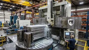
That combination of operations makes equipment capability at the machining partner a real constraint. Parkway-Kew Corporation operates in-house CNC turning, CNC milling, manual turning, and large-diameter grinding, with turning and milling capacity up to 72 inches in diameter and grinding capacity up to 65 inches diameter by 12 feet length.
That scale accommodates industrial components most shops cannot take on. Keeping machining and coating under one roof also eliminates the concentricity errors that arise when parts transfer between vendors.
CNC Precision Machining in Heavy Industrial Operations
Heavy industrial components don't just demand precision — they demand precision that holds up under extreme wear, heat, and load cycles. The following applications show where CNC turning, milling, and grinding do their most critical work.
Wire Drawing Blocks and Capstans
These components demand tight cylindrical tolerances and precise surface profiles. CNC turning establishes the correct substrate geometry before coating application (HVOF, plasma spray, or submerged arc welding). After coating, precision grinding brings the hardsurfaced block to final dimensional specification.
Parkway-Kew's proprietary Restore & Grind process takes this further: rather than grinding an entire block down to the deepest wear groove, only the drawline area is filled and blended with the original coating, enabling 5–7 lower-cost repair cycles before full recoating is needed.
Fracking Plunger Barrels
Concentricity is the critical variable for plungers. Conventional centerless grinding can leave the wear surface up to 0.015 inches out of concentricity with the clamping end — a problem that causes vibration, uneven wear, and scoring.
Parkway-Kew's post-coating finishing process corrects this by holding the clamping end during grinding, the same way the plunger is held in the pump. This aligns concentricity to the functional datum rather than a geometric approximation.
Sheaves, Festoon Wheels, and Large Industrial Rolls
These components combine turning for roundness and bore geometry with milling for keyways, flanges, and mounting features. Large-diameter capacity is essential — standard shops cannot handle wire drawing blocks or crane wheels that exceed their swing capacity.
Machining in Reconditioning Workflows
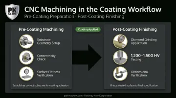
CNC machining serves two distinct roles in coating operations that are easy to overlook:
- Pre-coating: Machining establishes the dimensionally correct substrate that coating will adhere to. Surface geometry, flatness, and concentricity at this stage directly affect coating uniformity and bond strength.
- Post-coating: After HVOF tungsten carbide or plasma ceramic coatings are applied, machining (typically grinding) brings the coated surface to final specification. The hardness of these coatings — 1,200–1,500 HV for HVOF tungsten carbide — requires diamond grinding rather than conventional turning or milling.
Key Factors That Affect CNC Machining Outcomes
Material Properties
Harder materials require slower speeds, harder tooling grades, and more frequent tool changes. ISCAR specifies PCBN for steels at 50–70 HRC and ceramics for 45–60 HRC. Softer materials like aluminum allow faster cycles but are prone to deflection on thin sections. Using cutting parameters copied from a dissimilar material job is a common cause of surface finish failure and out-of-tolerance parts.
Machine Rigidity and Thermal Stability
HEIDENHAIN identifies thermal error as the primary cause of position error on modern machine tools — without proper position measuring and compensation, temperature rise alone can cause positioning errors up to 100 µm. Vibration in the spindle or workholding, worn bearings, and uncalibrated axes all shift dimensions during a run. High-precision work requires periodic machine calibration and, in many cases, temperature-controlled environments.
Cutting Parameters
Spindle speed, feed rate, depth of cut, and coolant application must all match the material and tool geometry. High-pressure coolant at 70 bar (1,015 psi) can allow 30–50% higher cutting speeds compared to flood coolant, per Sandvik data. Getting parameters wrong doesn't just affect surface finish — it causes tool breakage and scrapped parts.
Common Misconceptions
Understanding these variables also helps clear up a few persistent misconceptions about precision machining:
- "Tighter tolerance always means slower machining" — Modern toolpaths and optimized parameters can achieve ±0.001 in. at competitive cycle times
- "Turning and milling are interchangeable" — Part geometry determines the process, not operator preference or shop convenience
- "Precision is purely a machine capability" — Workholding rigidity, tooling condition, and programming quality drive the majority of dimensional outcomes
Conclusion
CNC turning and milling are complementary processes, each suited to distinct geometries and feature requirements, and both relying on computer-controlled material removal to deliver repeatable dimensional accuracy. Turning handles rotationally symmetric components. Milling handles prismatic and complex geometries. Many industrial components require both in sequence.
For operations in wire drawing, oil and gas, and heavy equipment, precision machining directly determines component life, coating adhesion, and operational reliability. The right machining partner brings:
- Appropriate equipment scale for large-diameter industrial components
- Process knowledge spanning turning, milling, and grinding
- Integrated machining and coating workflows, so parts never leave a single facility
Frequently Asked Questions
What is the difference between CNC milling and turning?
In CNC turning, the workpiece rotates while the cutting tool remains stationary, producing cylindrical and rotationally symmetric parts. In CNC milling, the cutting tool rotates while the workpiece stays fixed, producing flat surfaces, pockets, slots, and complex profiles. The right choice depends on the part's geometry and required features.
What is precision milling?
Precision milling is CNC milling performed to tighter-than-standard tolerances, typically ±0.002 in. (0.051 mm) or better, using optimized toolpaths, rigid fixturing, calibrated equipment, and matched cutting parameters. It's used for components where loose tolerances would cause fit failure, coating adhesion problems, or unacceptable wear in service.
How much does it cost to get a part CNC machined?
Cost depends on part complexity, material, tolerance requirements, quantity, and machine type. Setup costs are amortized over volume, so larger runs typically reduce per-part cost. Higher precision generally increases cost due to slower cycles and tighter process controls. Contact a machining partner directly with your part drawing and requirements for an accurate quote.
What tolerances can CNC turning and milling achieve?
Modern CNC turning and milling routinely achieve ±0.002 in. (0.051 mm) at precision grade. Reamed holes can reach ±0.0005 in. (0.0127 mm), and specialized ultra-precision setups on stable equipment can achieve tighter still. Achievable tolerance also depends on material, part size, feature location, and the stability of the machine environment.
Can CNC turning and milling be used for large industrial components?
Yes. CNC turning is regularly applied to large-diameter industrial parts such as wire drawing blocks, rolls, and sheaves. Specialized shops with large-bore capacity are required — Parkway-Kew Corporation, for example, handles CNC turning and milling up to 72 inches in diameter and grinding up to 65 inches diameter by 12 feet in length, well beyond the capacity of standard machine shops.