Get the sequence wrong and you're looking at oversized diameters, misaligned assemblies, or a part that won't seat flush against a mating flange. In industries where a fraction of a millimeter determines whether a wire drawing block runs smooth or chatters, this distinction isn't academic.
This article breaks down what separates turning from facing, where each one fits in a machining sequence, and how the two work together on real industrial components — including large-diameter wear parts restored at facilities like Parkway-Kew.
Key Takeaways
- Turning moves the tool parallel to the axis, shaping cylindrical or tapered diameters
- Facing moves the tool radially across the end, setting a flat reference face and controlling part length
- Most precision parts need both operations in sequence, not one or the other
- Facing typically comes first to "qualify" a rough surface before turning shapes the diameter
- Getting the sequence wrong on rough castings or forgings adds rework and scrap costs
Turning vs. Facing: Quick Comparison
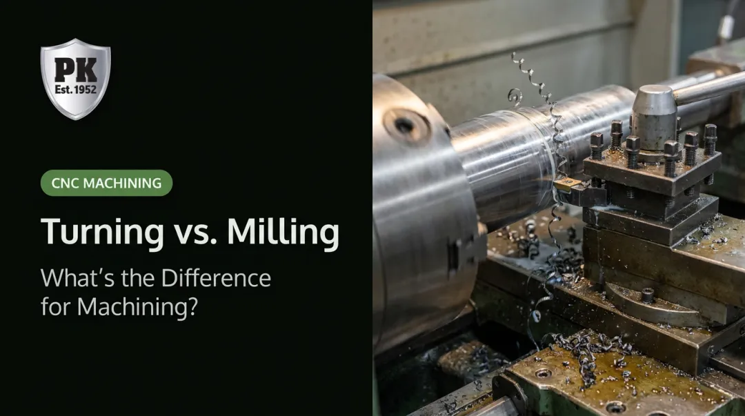
The clearest way to tell these operations apart is by tool travel direction and what dimension each one controls.
| Criterion | Turning | Facing |
|---|---|---|
| Tool movement | Parallel to the rotational axis | Radially, across the end face |
| Primary purpose | Shapes cylindrical, tapered, or grooved surfaces | Creates a flat end surface and sets part length |
| Dimension controlled | Outer/inner diameter | Overall length and squareness |
| Common defect risk | Chatter and vibration affecting diameter accuracy | Burrs and uneven flatness from poor tool selection |
According to Sandvik Coromant's external turning guidance, longitudinal turning feeds parallel to the workpiece axis and reduces diameter, while facing feeds radially toward the center at the workpiece end. That's the technical dividing line: everything else follows from it.
One nuance worth flagging: tooling overlap is real. Several factors determine which operation a holder actually performs:
- Insert shape and nose radius affect cutting behavior more than mounting position
- Entering angle determines whether a holder can handle both turning and facing
- Depth of cut settings often decide which operation a tool executes
Don't assume side-mounted tools always turn and end-mounted tools always face.
What is Turning?
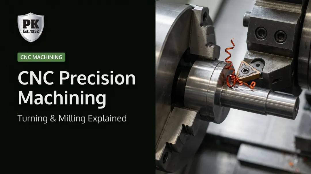
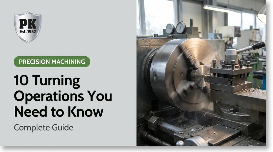
Turning is a lathe operation where a rotating workpiece gets shaped by a cutting tool moving along or radially into its axis. The tool removes material to bring the outer (or inner) diameter down to a target size, and it's the fastest route to rotationally symmetric geometry: shafts, tapers, threads, grooves.
There are two main flavors:
- Rough turning: prioritizes fast stock removal, tolerances are looser
- Finish turning: prioritizes surface quality and tight diametral precision
Getting the parameters right matters more than most people assume. On long, slender parts, incorrect feed rates or depth of cut invite vibration and chatter, which degrades both dimensional accuracy and surface finish.
Sandvik's own component-quality guidance notes that turning generates cylindrical and rounded forms using a single-point tool while the workpiece rotates. Achieving that form consistently, though, depends on tool selection and machine stability, not just the operation itself.
Where Turning Fits in a Manufacturing Sequence
Turning is usually the operation that brings a rough blank down toward its target diameter, ahead of finishing steps like grinding or polishing. You'll see it across:
- Automotive: drive shafts and axle components
- Aerospace: actuator components in high-alloy steel or Inconel, where chip control is critical
- Medical: implant components requiring tight, repeatable tolerances
- Industrial: bushings, rods, and rotating wear parts
Diametral tolerances for these parts follow the ISO 286 system, which defines tolerance grades and limit deviations for shafts and holes based on nominal size. There's no single "universal" turning tolerance: it depends on the size and grade specified on the drawing. Still, this framework is what shops reference when qualifying a turned diameter.
What is Facing?
Facing is a lathe (or mill) operation where the tool moves perpendicular to the rotational axis, flattening the end face of a workpiece. Instead of controlling diameter, facing controls length and squareness: it establishes a flat, precise reference surface that everything downstream gets measured from.
That reference-setting role is why Sandvik's turning quality guidance recommends starting with facing and a chamfer before anything else, since the face sets the component's reference point for every subsequent pass. Machine builders reinforce this too: Haas typically sets the Z-zero coordinate on the finished right-end face, making that surface the literal axial reference for the entire program.
Facing comes in a few forms:
- Lathe facing: single-point tool, workpiece rotates
- Face milling: rotating cutter, workpiece held stationary
- Spotfacing: a localized flat area machined around a hole, common in bolt or washer seating applications
Where Facing Fits in a Manufacturing Sequence
Facing is frequently the very first cut made on a rough casting or forging, and it "qualifies" one surface so every other dimension can be measured from something trustworthy. Typical applications include:
- Hydraulic and pipe flange faces
- Pipe and fitting ends requiring flat, sealed mating surfaces
- Gear blanks
- Large shaft ends where squareness affects downstream assembly
Flange work shows exactly why facing precision matters. ASME B16.5 specifies a gasket-contact surface roughness of 3.2 to 6.3 micrometers (125 to 250 microinches) for standard flange finishes. Miss that spec during facing, and you risk a leak path no gasket can compensate for — a costly failure mode in oil and gas or fluid-handling equipment.
Turning vs. Facing: Which One Should You Use?
The decision usually comes down to four factors:
- Desired geometry: a round profile calls for turning; a flat surface calls for facing
- Tolerance requirements: tight diametral tolerance points to turning; squareness or length tolerance points to facing
- Material condition: rough castings and forgings almost always need facing first to establish a clean datum
- Equipment available: a lathe handles both; a machining center may need a face mill for the flat surface
Practical guidance:
- Starting from rough stock? Face first to qualify a reference surface.
- Prioritizing diameter, threads, or tapers? Turn first.
- Working with pre-machined stock that already has a qualified reference? No blanket rule applies here; confirm sequence against the part drawing.
In practice, most precision components need both operations performed in sequence, not a single either/or choice. And for large-diameter or heavy-duty industrial components, turning and facing alone often aren't enough to restore original tolerances; these parts typically need specialized grinding or hardsurfacing to rebuild worn material.
Real-World Example: Turning and Facing in Precision Part Restoration
Wire drawing blocks and capstans take a beating. As wire is drawn across the block's surface at speed, it cuts a wear groove (the "drawline") that's typically the deepest point of wear on the entire component.
In a traditional regrind, the whole block has to be ground down to match that deepest groove. This strips away coating that was otherwise still serviceable and shrinks the block's diameter in the process.
That's the exact problem Parkway-Kew's Restore & Grind process was built to solve.
Here's how the restoration typically unfolds:
- Facing squares the block's ends, reestablishing a clean, precise reference before any diameter work begins
- Turning trues up the block's overall diameter and removes surface irregularities, using CNC and manual lathes rated up to 72 inches in diameter
- Targeted hardsurfacing rebuilds only the drawline wear zone and blends it seamlessly into the original coating, rather than stripping and recoating the entire block
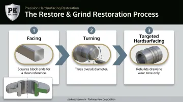
Because the process fills only the worn area instead of grinding the whole surface down, blocks can go through 5 to 7 lower-cost repair cycles before a full recoating is needed. That's a meaningful reduction in replacement frequency for wire mills running blocks around the clock.
This level of restoration is only possible thanks to Parkway-Kew's large-diameter grinding capability, which handles blocks up to 65 inches in diameter and 12 feet in length. Most general machine shops simply can't accommodate industrial-scale blocks and capstans at that size.
The bigger point: turning and facing aren't just new-part operations. Done right, they're what let a worn industrial component get a second, third, or seventh useful life instead of heading to scrap.
Have a batch of worn wire drawing blocks or capstans sitting in inventory? Contact Parkway-Kew to find out how their Restore & Grind process combines precision turning, facing, and hardsurfacing to extend service life.
Frequently Asked Questions
What does facing mean in machining?
Facing is a lathe or mill operation that creates a flat surface perpendicular to the rotational axis. It's typically used to set a part's overall length or establish a reference face for subsequent machining steps.
What is the difference between turning and facing?
Turning moves the tool parallel to the axis to control diameter, while facing moves the tool across the end face to control length and flatness. Both happen on a rotating workpiece, but they shape entirely different surfaces.
Can you face a part without turning it first?
Yes. Facing is often done first on raw stock to qualify a clean reference surface before any turning begins.
What tools are used for facing vs. turning?
Both operations can sometimes use the same versatile holder. However, turning generally favors sharper insert geometries for cylindrical cuts, while facing favors a broader nose radius for a smoother, flatter finish across the end.
Is facing only done on a lathe?
No. Facing is most common on lathes, but it's also performed on milling machines and machining centers using face mills, particularly for larger or non-rotationally-symmetric parts.
Which operation should be done first, turning or facing?
Facing is typically done first to establish a clean reference face, with turning following to shape the diameter. That said, the exact sequence can vary based on part design and the condition of the starting stock.