These lines usually trace back to a handful of fixable issues: stepover errors, insert wear, spindle misalignment, or rigidity problems. They are not an unavoidable cost of face milling.
This guide covers what causes lines between passes, how to diagnose and fix them step-by-step, when they're purely cosmetic versus a functional defect, and how to stop them from coming back.
Key Takeaways
- Stepover, insert height, tram error, and tool deflection cause most visible pass lines
- Most cases are fixable through stepover math, tooling checks, and calibration
- Diagnose in order: map the pattern, then check stepover, inserts, tram, and rigidity
- Lines are cosmetic on general fabrication but functional on sealing surfaces and wear components
What Are Face Milling Lines Between Passes?
Face milling lines are visible ridges or witness marks left where adjacent cutter passes meet or fail to blend fully. Some surface texture is inherent to the process.
According to Sandvik Coromant's surface generation guide, a face-milled surface is generated axially and replicates the bottom geometry of the insert. An insert with a corner radius produces cusps, and their size depends on that radius and the feed rate.
That's normal texture, not a defect. The problem starts when marks become pronounced, irregular, or unevenly spaced rather than a light, uniform pattern.
Light Texture vs. Real Setup Problems
Here's the distinction that matters:
| Pattern | What You'll See |
|---|---|
| Expected | Fine, evenly spaced cusps matching the insert geometry and feed |
| Problem | Visible ridges, deeper grooves at pass boundaries, or marks that vary in spacing or depth |
This shows up most on large flat or cylindrical parts machined in multiple stepover passes, including plates, tables, wire drawing blocks, and capstans. On these parts, pronounced lines affect measured Ra, trap debris, and wear unevenly under load, making this a functional concern beyond appearance.
Common Causes of Face Milling Lines Between Passes
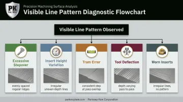
Most visible line patterns trace back to a small number of predictable root causes. Spotting the pattern narrows down the cause fast, before you touch a single machine parameter.
The table below maps each cause, from stepover to worn inserts, to its telltale symptom, so you can quickly match what you're seeing on the part to the likely root cause.
| Cause | What Happens | Symptom |
|---|---|---|
| Excessive Stepover (Radial Depth of Cut) | Stepover set too large relative to cutter diameter, insert corner radius, or wiper flat width leaves unmilled scallops between passes | Evenly spaced, regular ridges matching the stepover distance almost exactly |
| Insert Height Variation or Runout | Inserts seated at different axial heights cut at different depths; the lowest insert generates the finished surface | Irregular, unevenly spaced lines that change depth around the pass |
| Spindle-to-Table Misalignment (Tram Error) | A spindle that isn't perfectly perpendicular to the table cuts deeper on one side of the cutter than the other | Consistent step line at every pass overlap, often called back-cutting |
| Tool Deflection & Machine Rigidity Issues | Long tool overhang, worn spindle bearings, or weak workholding let the cutter deflect mid-cut | Depth varies pass to pass instead of staying constant |
| Worn, Chipped, or Mismatched Inserts | Uneven wear, chipped edges, or mixed insert batches change the effective cutting geometry from tooth to tooth | Irregular lines with no consistent pattern |
How to Eliminate Lines Between Passes (Step-by-Step)
Adjusting parameters blindly wastes material and machine time. Work through this sequence to isolate the actual cause before applying a fix.
Inspect and map the line pattern. Measure the spacing between lines and compare it to your programmed stepover value. A uniform pattern points to stepover; an irregular one points to runout, tooling, or alignment issues.
Verify stepover and cutter/insert selection. Recalculate stepover based on cutter diameter, insert corner radius or wiper flat width, and target Ra. Reduce stepover or switch to a cutter with wiper inserts to flatten the finish between passes.
Check insert runout and seating. Use a dial indicator on each insert to measure axial height differences across the cutter body. Clean insert pockets, replace worn shims, torque to spec, and replace the full insert set if wear is uneven.
Tram the spindle to the table. Run a tramming check with an indicator sweeping the table to confirm spindle-to-table perpendicularity. Haas's documented spindle sweep procedure places the stylus 5 inches from spindle center, checking readings every 90 degrees and adjusting head shims until error falls within tolerance.
Optimize feed, speed, and tool rigidity. Reduce tool overhang and confirm you're using the correct toolholder for the job. Adjust feed per tooth to keep chip load consistent across the cut.
Take a finishing pass and validate. Run a light spring pass after adjustments and measure the surface with a profilometer. Confirm lines are eliminated or fall within the required Ra tolerance before releasing the part.
Skipping straight to step 6 without steps 1 through 5 is how shops burn through material chasing a symptom instead of a cause.
When Are Lines Between Passes Cosmetic vs. a Functional Problem?
Not every visible line is a defect. ASME B46.1 draws a clear distinction between surface texture (roughness, waviness, lay) and form error. Whether a line matters depends entirely on what the part does.
- General structural or fabricated parts: Lines within the specified finish tolerance are cosmetic — no further action needed.
- Precision mating or sealing surfaces (gaskets, bearing seats, flanges): Visible lines are a functional defect requiring re-finishing, regrinding, or a corrected finishing pass before the part goes into service.
- Precision wear components (wire drawing blocks, capstans, festoon wheels): Lines here aren't just an inspection headache. They can mark or damage the wire as it runs and reduce coating adhesion over time.
This is exactly where Parkway-Kew's in-house work comes in. With CNC milling and turning up to 72 inches in diameter and large-diameter grinding up to 65 inches diameter by 12 feet in length, our shop handles the oversized cylindrical parts where pass lines are hardest to correct on standard equipment.
For wire drawing blocks specifically, our proprietary Restore & Grind process fills in only the drawline wear area and blends it seamlessly with the surrounding original coating, rather than grinding the entire block down to the depth of the deepest groove.
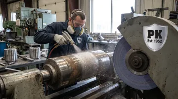
Because Parkway-Kew coatings are applied at enhanced thickness, most blocks support 5 to 7 Restore & Grind cycles before a full recoating is needed. This restores a blemish-free surface without the cost of full part replacement.
Preventive Best Practices
A few habits prevent most pass-line problems before they start:
- Calculate stepover from data sheets, not defaults. Pull the insert manufacturer's chip-load and stepover recommendations directly into your CAM template so operators can't override them with generic presets.
- Schedule tramming and runout checks proactively. Add spindle tramming and insert runout checks to a monthly PM schedule, not a reactive one triggered by a bad part on the table.
- Replace insert sets as matched sets. Avoid mixing brands or wear levels across a cutter body, and run a test pass to verify finish before committing to full production.
Building these checks into standard operating procedure catches stepover errors, tramming drift, and insert mismatches before they scar a workpiece.
Frequently Asked Questions
What does milling mean?
Milling is a machining process that uses a rotating multi-tooth cutter to remove material from a workpiece. It produces flat, contoured, or slotted surfaces depending on the cutter and toolpath used.
What are the two types of milling?
The two primary categories are face milling and peripheral (slab) milling. Face milling cuts flat surfaces using the cutter's end face, while peripheral milling uses the cutter's circumference to produce slots, grooves, and deeper features.
What are milling marks?
Milling marks, sometimes called witness or revolution marks, are the repeating surface marks left by the cutter's edges as they pass over the workpiece. Some are a normal byproduct of the process; pronounced ones signal a setup issue.
What is the difference between milling and machining?
Machining is the broad category of material-removal processes, including turning, drilling, grinding, and milling. Milling is one specific method within that category, using a rotating cutter against the workpiece.
Why does my face mill leave lines between passes?
The most common causes are excessive stepover for the cutter and insert geometry, insert height variation or runout, spindle misalignment, and tool deflection from excess overhang or a weak setup.
How do you get rid of lines in face milling?
Reduce stepover, verify insert runout and seating, tram the spindle to the table, and take a proper light finishing pass. Together these steps eliminate visible lines in nearly every case.