Introduction
A coating is only as good as the number it produces on a hardness tester. HVOF tungsten carbide, plasma-sprayed ceramics, and weld overlays are each engineered to hit a specific hardness target.
That number predicts wear life in abrasive environments like wire drawing blocks, capstans, fracking plungers, and festoon wheels.
The problem is that hardness testing gets treated as an afterthought. Many QC teams struggle with inconsistent readings caused by the wrong indenter load, a curved surface tested like a flat one, or a single spot check standing in for a real inspection.
The result: premature wear in the field, unplanned downtime, or parts rejected that were actually fine.
This guide covers the equipment and methods used to measure coating hardness accurately: Rockwell, Vickers microhardness, and portable field testing. It also explains how to read the results, avoid common mistakes, and test safely.
TL;DR
- Hardness testing verifies a coating meets its wear-resistance spec before a part goes back into service.
- Rockwell and Vickers are the industrial standards for coatings — not automotive pencil or Mohs scales.
- Method choice depends on coating thickness, part size, and whether destructive prep is acceptable.
- Always compare readings against a documented spec range, never judge them in isolation.
- Calibration and surface prep prevent most bad readings.
What You Need to Measure Coating Hardness
Coating type drives everything here. A thick sub-arc weld overlay behaves nothing like a 0.010-inch HVOF layer under an indenter, and choosing equipment without accounting for that difference is where most testing errors start.
You also need to know upfront whether the part can be cut for a cross-section or whether it has to stay intact.
Tools and Indicators Required
A properly equipped hardness testing setup typically includes:
- Bench Rockwell tester with diamond cone or ball indenter for thick metallic deposits
- Vickers microhardness tester with measuring microscope for thin coating cross-sections
- Portable rebound or UCI tester for large or installed parts that can't be sectioned
- Certified calibration blocks matching the expected hardness range
- Mounted, polished cross-section samples for micro-testing
Coating thickness dictates load selection. Push too much load into a thin coating and the indenter drives past the coating into the substrate. You end up measuring the base metal, not the coating you actually applied.
Preconditions and Setup
Before any indenter touches the part, a few conditions have to be met:
- Clean, flat, representative surface — no edges, repaired zones, or contaminated areas
- Stable, level mounting for bench testing; curved surfaces (like wire drawing block bores or capstan faces) need curvature correction factors for portable testers
- Adequate lighting and magnification to read indentation size accurately during Vickers testing
Skipping any of these introduces scatter into your readings before you've even applied the test load.
Methods to Measure Coating Hardness
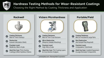
Which method you use comes down to three questions: how thick is the coating, can the part be cut, and is this a lab test or a field check on an installed component? Here's how the three standard methods stack up.
Method 1: Rockwell Hardness Testing (HRC)
Rockwell measures resistance to indentation using a diamond cone or ball under a fixed load. It's the go-to for thicker coatings like weld hardfacing overlays, where there's enough material depth to keep the substrate out of the reading.
Tools needed: Bench-top Rockwell tester, diamond cone indenter, calibration blocks.
Steps:
- Prepare a flat, clean test area on the coated part
- Apply the minor load, then the major load, following the applicable standard procedure
- Record the HRC value and average 3-5 readings across the surface
Rockwell is fast, standardized, and well suited to thick hardfacing deposits. As a general rule of thumb, coating thickness should be roughly 10 times the expected indentation depth for a diamond indenter, per ASTM E18 guidance on Rockwell testing.
Below that threshold, the reading gets skewed by whatever's underneath. That makes Rockwell a poor fit for thin thermal-sprayed layers.
Method 2: Vickers Microhardness Testing (HV)
Vickers uses a diamond pyramid indenter at low load on a polished cross-section, which is what makes it capable of measuring coating hardness independent of the substrate underneath.
Tools needed: Microhardness tester, mounted and polished cross-section sample, measuring microscope.
Steps:
- Cut, mount, and polish a cross-section of the coated sample
- Select a load appropriate to coating thickness, using lighter loads for thin thermal-sprayed layers
- Measure the indentation diagonal under a microscope and calculate the HV value
This method is highly accurate for thin coatings such as HVOF tungsten carbide. It can reveal hardness gradients through the coating layer that a single bulk reading would never show.
The trade-off: it requires destructive sample prep and lab equipment, so it's not something you'd do on every part shipped.
Method 3: Portable/Field Hardness Testing (Rebound or UCI)
Handheld devices estimate hardness directly on large or installed parts without cutting a sample. That's a real advantage when you're dealing with a part too big to bring into a lab, or one that's already back in service.
Tools needed: Portable hardness tester, calibration/verification block, curvature correction reference.
Steps:
- Calibrate the device against a reference block matching the expected hardness range
- Hold the probe perpendicular to the coated surface and take multiple readings across the test area
- Average the readings and apply curvature correction when testing curved surfaces
Portable testing is non-destructive and lets you check finished parts directly. This is exactly the kind of verification built into a restoration workflow like Parkway-Kew's Restore & Grind process for wire drawing blocks.
It's slightly less precise than lab-based methods, though, and more sensitive to operator technique than either Rockwell or Vickers.
How to Interpret the Results
A hardness number by itself doesn't tell you much. It only means something when you compare it to a documented specification range, and misreading that comparison is exactly how good parts get rejected or under-spec parts slip through.
Here's how to categorize what you're seeing:
| Reading Type | What It Means | Action |
|---|---|---|
| Normal/Acceptable | Falls within the documented spec range | Approve for service or shipment |
| Minor Deviation | Small variance near tolerance edge | Retest at multiple points before deciding |
| Out-of-Spec | Significantly below spec | Reprocess, grind, or reapply the coating |
Out-of-spec readings usually trace back to one of three root causes:
- Incomplete deposition during application
- Incorrect process parameters, such as temperature, pressure, or spray distance
- Substrate interference skewing the reading
Each is a process problem, so the fix is correcting the process, not averaging away the bad reading.
For critical wear applications like fracking plungers, wire drawing blocks, or anything where a coating failure means unplanned downtime, log every reading against location and part ID. That traceability record is what lets you trace a field failure back to a specific test point months later, instead of guessing at what went wrong.
Common Errors and Safety Best Practices
Most bad hardness readings trace back to a handful of repeatable mistakes.
Common testing errors:
- Testing on a curved, rough, or uncleaned surface without applying correction factors
- Using too high an indenter load on thin coatings, pulling the substrate into the reading
- Skipping calibration against a certified reference block before testing
- Relying on a single reading instead of averaging multiple points
Fixing these errors improves reading accuracy, but protecting the technician matters just as much during testing.
Safety practices:
- Follow lockout/isolation procedures before testing hardness on installed equipment. OSHA's lockout/tagout standard requires isolating and dissipating stored energy before servicing.
- Secure the part on a stable, level surface before applying any test load
- Wear appropriate PPE, including safety glasses and gloves, when handling indenters or cutting cross-section samples
- Keep the test area free of oil and debris to prevent false readings
Conclusion
Accurate hardness measurement is the difference between a coating that performs to spec and one that fails early in the field. Choosing the right method (Rockwell for thick overlays, Vickers for thin cross-sections, portable testing for installed parts) matters just as much as running the test correctly.
Parkway-Kew has been building wear-resistant coatings for wire drawing blocks, capstans, and fracking components since 1952. Hardness verification is part of how HVOF, plasma spray, and Restore & Grind processes confirm a part is ready to go back into service. Getting that number right, consistently, is what keeps parts running instead of coming back early.
Frequently Asked Questions
What is the hardness of coating?
Coating hardness is a measure of resistance to indentation, scratching, or deformation. The specific scale used (Rockwell, Vickers, or pencil hardness) depends on the coating type and thickness.
What are the three types of hardness?
The three types are scratch, indentation, and rebound hardness. Scratch hardness resists scratching, indentation hardness resists permanent deformation under load, and rebound hardness reflects how a material responds to impact. Rockwell and Vickers are indentation methods; Leeb is a rebound method.
What is 9H hardness in ceramic coating?
9H refers to the pencil hardness scale commonly used for thin automotive ceramic and paint coatings. This scale doesn't translate to industrial metal or thermal-sprayed coatings, which use Rockwell or Vickers instead.
What hardness scale is used for HVOF and thermal spray coatings?
Rockwell C or Vickers hardness are the standard scales for HVOF and thermal spray coatings, chosen based on coating thickness and hardness range. Vickers is typically used for thinner layers since it isolates the coating from the substrate.
Can coating hardness be tested without damaging the part?
Yes. Portable rebound or UCI testers allow non-destructive field testing directly on the part. Lab-based Vickers or Rockwell testing offers higher precision but requires cutting a sample.
How often should coating hardness be verified in industrial applications?
Verify hardness after every application or reconditioning cycle, and periodically during service for critical wear parts. The exact interval should follow the part's governing specification or a risk-based maintenance plan.